
CarderPlanet
Professional
- Messages
- 2,549
- Reaction score
- 722
- Points
- 113
Published for informational purposes only.
Today we will assemble a model of a radio microphone that we can listen to with any FM radio receiver (be it a radio or your phone with radio support). Our beetle will work approximately within a radius of 50 meters and be powered by a 3.7 V battery (you can use a CR2032 or a packaged battery. The first one will last for several days, and the second one much longer).
The scheme of such a beetle is a lot where there is. There is even a video on how to put it together. But I’m a lazy person and I don’t want to collect what may not work. Therefore, I will first simulate the circuit, measure all the parameters, and only then start assembling the device.
Well, let's get started ...
The general scheme of the beetle looks like this:
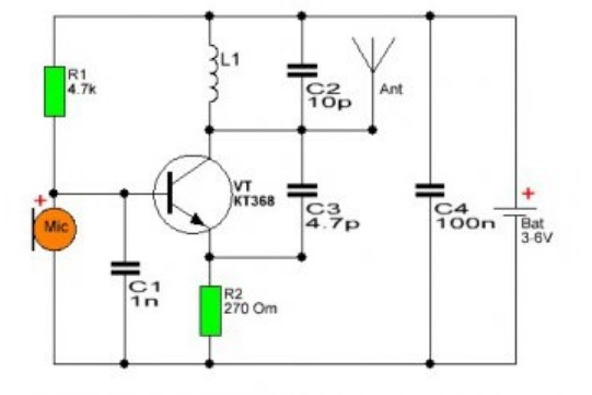
The author declares that adjusting the C2 capacitance gives the following frequencies:
10 p - 88 MHz, 8.2 p - 95 MHz, 6.8 p - 104 MHz
Took note. Then the problems begin. It is impossible to simulate this device as it is! At least because the KT368 transistor, microphone and antenna are simply absent in any circuit design program! They are simply not there. What to do?
I found a way out.
We have a NPN low-power high-frequency transistor. We will replace it with an analogue (you will see it in the diagram below. The entire list of details will be at the end of the article).
We will replace the microphone with a pulse generator. Please note that the generator will give us monotonic pulses with the same frequency and amplitude. People don't talk like that! We have our own timbre, we speak louder and softer and the frequency is different. Our speech is a wave constantly changing over time. The generator doesn't behave like this, so don't be surprised at the oscillograms below. The generator behaves the same at any time interval, and that's enough for us.
What about the antenna? It was possible to replace it with an optocoupler (read in any source other than Wikipedia) what it is. This is a very simple device. I will be using an NPN transistor, a resistor, an auxiliary power supply and a pair of LEDs. It is NOT NECESSARY to assemble this part of the circuit. This is only necessary for design in circuit simulation programs!
Let's take a look at the modified device diagram:
I will shade the part of the circuit that measures the antenna:
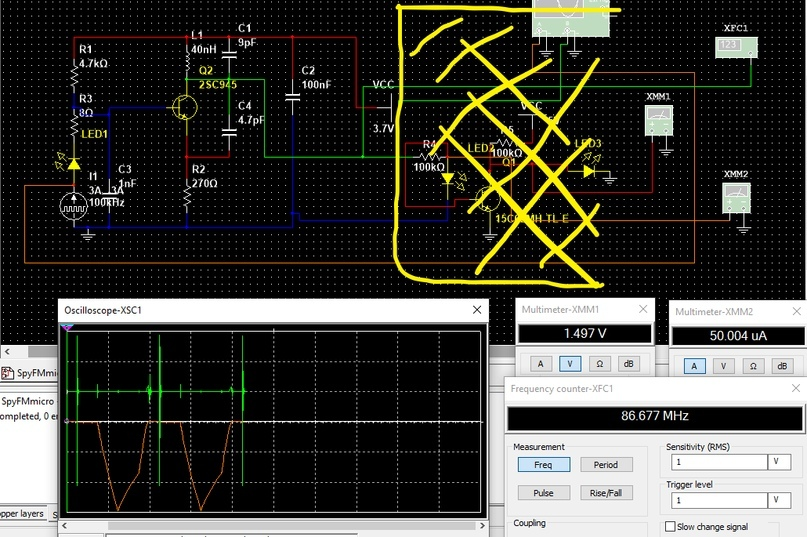
You do not need to assemble this part of the circuit. This is only required for simulation.
Well, we see our 100 kHz pulse generator:
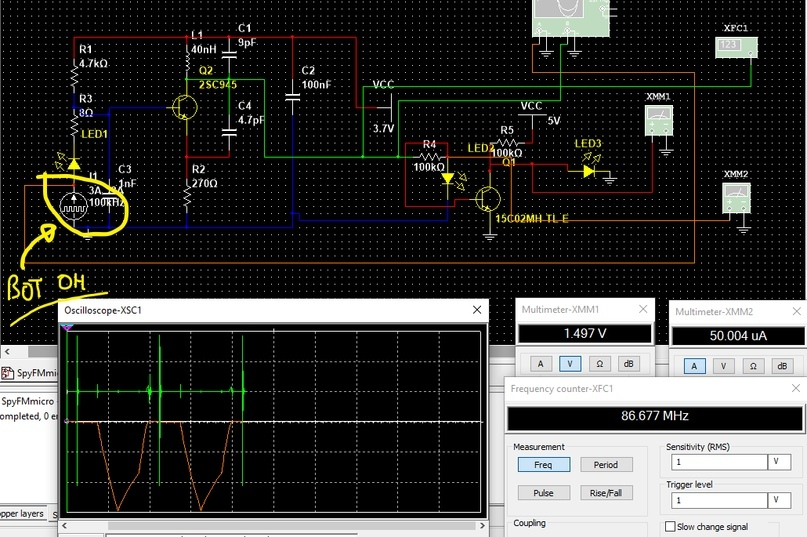
We put this generator instead of a microphone. On a real device, put a microphone in its place.
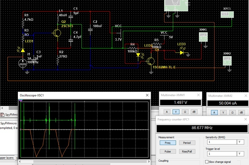
In the diagram, we see a green wire. This is where you need to solder the antenna. We are not looking at the devices yet.
What is important in this scheme? Let's take a look at the oscillator (our oscillatory circuit). We need to set the value of the inductance for the coil (the author does not have it) and the value of the capacitor (on my circuit it is C1). Thanks to these two parameters, we will be able to control the frequency of the output signal.
To begin with, I substituted the values of the author and got only 45 MHz at the output. This is not enough! Our radio picks up from about 85 MHz. We need to increase the frequency.
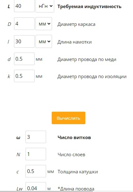
I selected the inductance of the coil 40 nH. This is provided that we wind the copper wire on a 4 mm gel pen rod, the length of the wire is 30 mm and the diameter of the wire itself is 0.5 mm. It turns out that we only need 3 turns. By the way, such a coil is sold in radio parts stores, it is cheap and the manufacturer claims a frequency of 100 MHz ± 5%. You can buy it, or you can wind it yourself.
Next, we adjust the conder.
Let's say we have a capacitance of 9 pF.
Let's connect a voltmeter, a frequency meter to the antenna and an oscilloscope to our generator and antenna.
On the oscilloscope, the red color shows the pulse from the generator (microphone), and green from the antenna.
The antenna voltage is 1.5 V, the frequency is 86.6 MHz, and the current is approximately 50 μA. Not bad.
Now let's increase the frequency of the output signal:
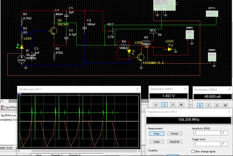
We changed the capacitance of C1 to 6 pF. As a result, we got 108.3 MHz. Now you can play with the C1 conductor so that you can tune the optimal frequency, and you can also use a variable capacitor. He will have a handle, twisting which you can change the capacity, which is also very convenient.
We need about 200 - 400 mm (20 - 40 cm) antenna length. It's just a piece of copper wire.
You can calculate the number of turns on a coil using this calculator:
I counted like this:
As a result, we need:
1 microphone
Resistors 8 ohm, 270 ohm, 4.7 kohm
40 nH inductor
Capacitors 1 nF, 4.7 pF, 100 nF, and the one that we will select (you can use a trimmer), for example 6 pF
The transistor I have is 2SC945. You can also use KT368, BC547, KT3102, C9018 if you find it.
A piece of copper wire 20-40 cm.
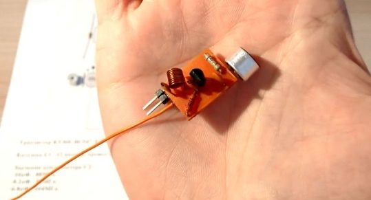
One of the models looks like this:
Today we will assemble a model of a radio microphone that we can listen to with any FM radio receiver (be it a radio or your phone with radio support). Our beetle will work approximately within a radius of 50 meters and be powered by a 3.7 V battery (you can use a CR2032 or a packaged battery. The first one will last for several days, and the second one much longer).
The scheme of such a beetle is a lot where there is. There is even a video on how to put it together. But I’m a lazy person and I don’t want to collect what may not work. Therefore, I will first simulate the circuit, measure all the parameters, and only then start assembling the device.
Well, let's get started ...
The general scheme of the beetle looks like this:
The author declares that adjusting the C2 capacitance gives the following frequencies:
10 p - 88 MHz, 8.2 p - 95 MHz, 6.8 p - 104 MHz
Took note. Then the problems begin. It is impossible to simulate this device as it is! At least because the KT368 transistor, microphone and antenna are simply absent in any circuit design program! They are simply not there. What to do?
I found a way out.
We have a NPN low-power high-frequency transistor. We will replace it with an analogue (you will see it in the diagram below. The entire list of details will be at the end of the article).
We will replace the microphone with a pulse generator. Please note that the generator will give us monotonic pulses with the same frequency and amplitude. People don't talk like that! We have our own timbre, we speak louder and softer and the frequency is different. Our speech is a wave constantly changing over time. The generator doesn't behave like this, so don't be surprised at the oscillograms below. The generator behaves the same at any time interval, and that's enough for us.
What about the antenna? It was possible to replace it with an optocoupler (read in any source other than Wikipedia) what it is. This is a very simple device. I will be using an NPN transistor, a resistor, an auxiliary power supply and a pair of LEDs. It is NOT NECESSARY to assemble this part of the circuit. This is only necessary for design in circuit simulation programs!
Let's take a look at the modified device diagram:
I will shade the part of the circuit that measures the antenna:
You do not need to assemble this part of the circuit. This is only required for simulation.
Well, we see our 100 kHz pulse generator:
We put this generator instead of a microphone. On a real device, put a microphone in its place.
In the diagram, we see a green wire. This is where you need to solder the antenna. We are not looking at the devices yet.
What is important in this scheme? Let's take a look at the oscillator (our oscillatory circuit). We need to set the value of the inductance for the coil (the author does not have it) and the value of the capacitor (on my circuit it is C1). Thanks to these two parameters, we will be able to control the frequency of the output signal.
To begin with, I substituted the values of the author and got only 45 MHz at the output. This is not enough! Our radio picks up from about 85 MHz. We need to increase the frequency.
I selected the inductance of the coil 40 nH. This is provided that we wind the copper wire on a 4 mm gel pen rod, the length of the wire is 30 mm and the diameter of the wire itself is 0.5 mm. It turns out that we only need 3 turns. By the way, such a coil is sold in radio parts stores, it is cheap and the manufacturer claims a frequency of 100 MHz ± 5%. You can buy it, or you can wind it yourself.
Next, we adjust the conder.
Let's say we have a capacitance of 9 pF.
Let's connect a voltmeter, a frequency meter to the antenna and an oscilloscope to our generator and antenna.
On the oscilloscope, the red color shows the pulse from the generator (microphone), and green from the antenna.
The antenna voltage is 1.5 V, the frequency is 86.6 MHz, and the current is approximately 50 μA. Not bad.
Now let's increase the frequency of the output signal:
We changed the capacitance of C1 to 6 pF. As a result, we got 108.3 MHz. Now you can play with the C1 conductor so that you can tune the optimal frequency, and you can also use a variable capacitor. He will have a handle, twisting which you can change the capacity, which is also very convenient.
We need about 200 - 400 mm (20 - 40 cm) antenna length. It's just a piece of copper wire.
You can calculate the number of turns on a coil using this calculator:
I counted like this:
As a result, we need:
1 microphone
Resistors 8 ohm, 270 ohm, 4.7 kohm
40 nH inductor
Capacitors 1 nF, 4.7 pF, 100 nF, and the one that we will select (you can use a trimmer), for example 6 pF
The transistor I have is 2SC945. You can also use KT368, BC547, KT3102, C9018 if you find it.
A piece of copper wire 20-40 cm.
One of the models looks like this: