
Hacker
Professional
- Messages
- 1,041
- Reaction score
- 851
- Points
- 113
The content of the article
When you decide to overclock, you will immediately face two main problems. First, you need to somehow bring the hardware out of the normal mode of operation and at the same time maintain stability. Secondly, the resulting performance gain has yet to be measured in order to assess the real benefits of all the tweaks.
Of course, when it comes to overclocking a gaming PC, then everything is often trivial. Many manufacturers of processors and video cards release their own utilities to increase the voltage and clock speeds, so in the end it all comes down to moving the sliders in the program window. After that, it remains only to run the benchmark built into the game and observe the growth of the numbers (FPS matters, yeah).
But have you ever wondered how it all actually works? And what do you need to know to achieve truly outstanding results? I'll try to demonstrate with an example.
Hardware part
Low-level hardware overclocking will be easiest to show on a regular microcontroller. Surely you are familiar with Arduino - this tiny board turned the world of makers, hackers and everyone involved. It has a minimum of components: a quartz resonator, an ATmega328P microcircuit and a power regulator. And yet it is almost a computer. So it can be overclocked too!
However, today I am tuned to the maximum result, and some measly 16 MHz clock frequency does not interest me at all. Put the Arduino aside and take the Nucleo-144 board based on the STM32H743.
If you try to find a suitable analogy from the world of personal computers, then we have the Core i9, without a doubt. The ARM core (Cortex-M7) runs at a staggering 480 MHz, which is exactly 15 times faster than the original Arduino Uno. Moreover, it houses two megabytes of permanent flash memory and a whole megabyte of RAM. Performance is added by the program cache and data cache (16 KB each), as well as the built-in accelerator of the ART code execution.
Today there are two versions of this debug board. Initially, the H743ZI with the ST-Link V2-1 programmer and revision Y microcontroller appeared in the Nucleo-144 model line. It supported regular operation "only" at 400 MHz. But after a few months, the manufacturer managed to optimize the crystal circuit and began to release the H7 microcontrollers of a new revision V with a base frequency of 480 MHz. They formed the basis for the H743ZI2 board. In addition, the programmer was also updated - now it is ST-Link V3E with the possibility of in-circuit emulation.
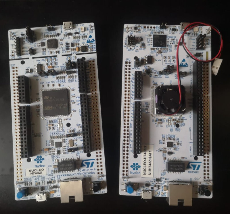
So, if you choose the same board for yourself, be extremely careful, outwardly they are very similar and are made on the same white PCB. And there are no special differences in other parameters: Arduino, Morpho, Ethernet and USB connectors are present on both boards.
New IDE
Even very good hardware can be useless if there is no suitable software for it. Fortunately, ST Microelectronics understands this as well, so relatively recently they made their own CubeIDE. However, it is difficult to call it completely new. In fact, this is an add-on to Eclipse, which should delight users familiar with Atollic TrueStudio and AC6 Workbench environments.
The IDE is not only free and available on all major platforms (Windows, Linux and macOS are supported), but also allows you to use modern debugging and tracing tools (OpenOCD, GDB) out of the box, as well as configure microcontroller peripherals in just a couple of clicks mice.
After installing and configuring the toolchain, you can proceed to testing. We have to port the benchmark source codes to our architecture and implement a couple of platform-dependent functions. Since the operating system is completely optional in this case, you will need to redefine the function printfto display debugging information and the current time function to calculate the test result.
Setting up the project
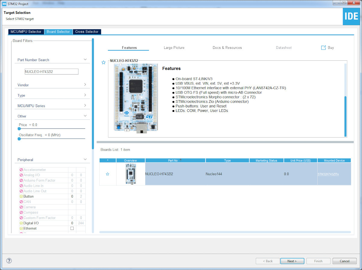
After creating the project for the Nucleo-H743ZI2 development board, we need to change a few defaults.
The peripheral configuration window has two useful areas (in fact, there are much more of them, but we are now specifically interested in these): Pinout & Configuration and Clock Configuration. Peripheral functions can be specified from the right-click dropdown menu. More fine tuning is done in the System view window. A graphical representation of the clock tree can be found in the Clock Configuration tab.
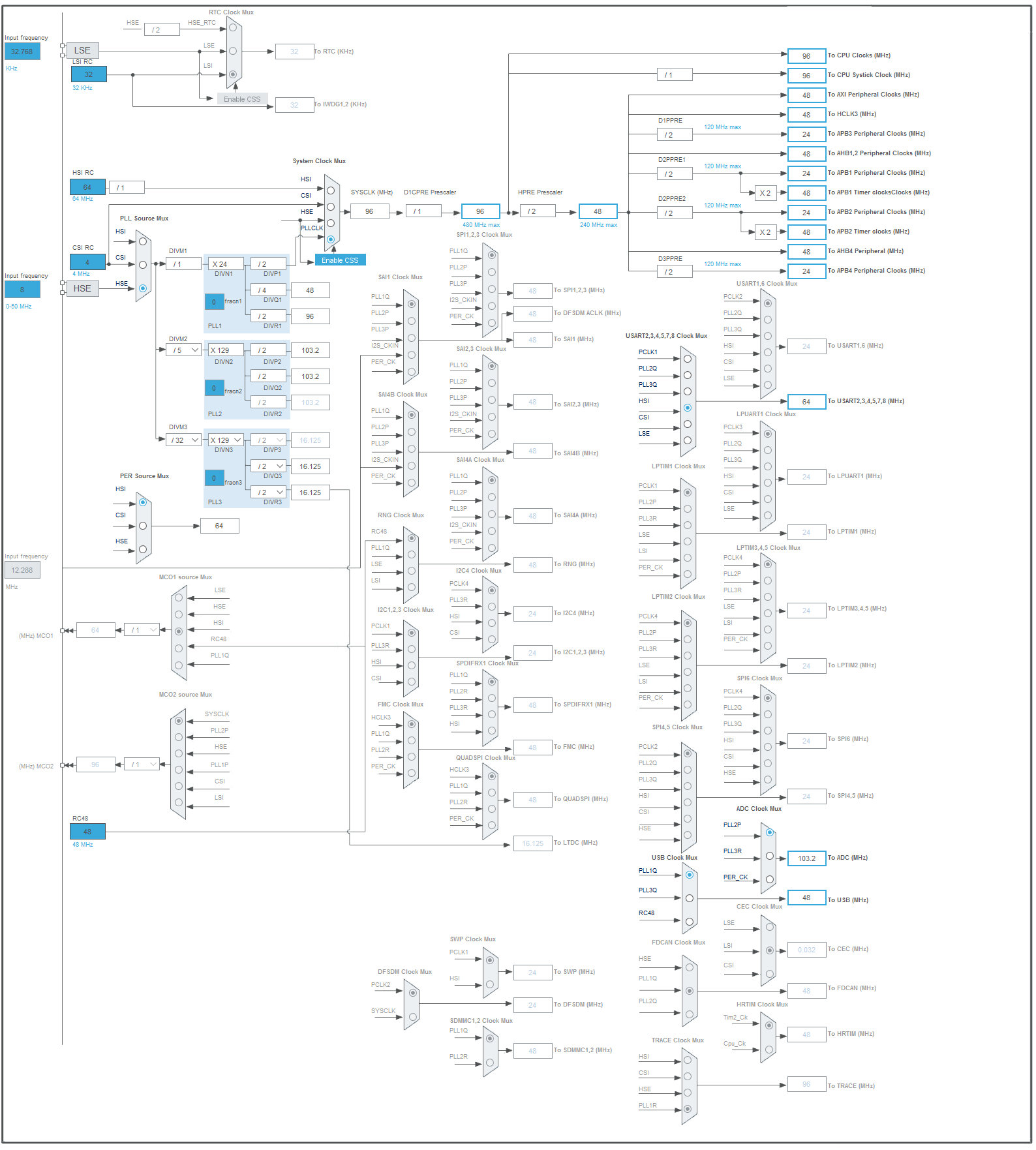
Notice that further frequency tuning system as the primary source will be used a PLL, clocked by an external crystal HSE. In our case, it is already on the development board and has a nominal value of 8 MHz.
The maximum possible clock frequency of the core and the system bus can be provided by installing DIVM1 = 1and dividers DIVP1 = 7. The multiplier value DIVN1will have to be increased until the microcontroller is stable. Dividers HPRE, D1PRE, D2PPRE1, DRPPRE2and D3PPREis set at two, the rest will leave the default.
We must not forget about nutrition. The PLL unit operates from a linear regulator, the mode of which [VOS0...VOS5]programmatically sets the voltage level from 1.35 to 0.7 V. In addition, if necessary, you can supply external power Vcore, but only if it does not exceed 1.4 V.
As you can imagine, increasing the voltage allows you to achieve higher clock frequencies. This is due to the fact that the transistors in the circuit begin to change their state faster (the duration of the leading and trailing edges of the signal is reduced).
Let's add a timer to calculate the time TIM2. With the divider configuration installed, it will operate at half the system frequency SYSCLK. This completes the setting of the parameters, so save the settings and start generating the project.
Now you have to specify the compiler and linker. This can be done in the menu Project → Properties → C / C ++ Build → MCU Settings (MCU GCC Compiler, MCU GCC Linker). And for purely academic purposes, I propose to first leave the optimizations at the level -O0(optimization is disabled).
In the next step, we need to ensure that the function works correctly printf. To do this, we include the header file <stdio.h>and add the compilation key -u _printf_floatfor the linker. It remains only to implement the function of displaying characters:
In addition, let's redefine the function for setting the clock frequency:
In the listing above, of particular interest is the adjustment of the PLLN multiplier, which affects the core clock speed (which directly affects the performance). Also pay attention to the procedure for selecting the power supply for the PLL __HAL_PWR_VOLTAGESCALING_CONFIGand setting the timings for the flash memory HAL_RCC_ClockConfig.
The timer setting function TIM2can be implemented as follows:
Now, at any point in our code, we can find out the number of microseconds that have passed since the start of the timer. To do this, it will be enough just to refer to the register TIM2 → CNT.
Benchmarks
Overclocking itself is unlikely to be of interest to anyone, its results are much more important: how many percent of performance you actually managed to get and whether it allowed your neighbor to wipe his nose. And for this it would be good to first agree on general criteria for evaluating the system.
Surprisingly, it's not that easy. Everyone has different tasks, and there are even more ways to solve them. Fortunately, over the years, everyone seemed to be able to agree, but it was a whole story.
A brief history of the origin of parrots
Whetstone is considered to be the first widely used performance test, which was released in November 1972. It used 1 MWIPS as its reference unit, which corresponds to one million operations per second on the DEC VAX-11/780 architecture. The test included 150 simple expressions, divided into eight blocks, which were executed in the main loop.
It was assumed that the small size of the test would allow it to completely fit into the L1 cache of computers and ignore the advantages of L2. Whetstone was not designed to use optimization compilers, which eventually led to confusion in calculating the results. The "advanced" compilers that appeared in the 1980s have learned to optimize address transitions, virtually doubling benchmark performance.
If the Whetstone test was not tied to any operating system (and was also executed on barebone platforms), then the Dhrystone test developed in 1984 was intended to assess the performance of computing systems on the Unix kernel and used, for example, system library functions for working with time.
Unlike Whetstone, which focuses on working with floating point numbers, Dhrystone specialized in working with integer and string variables. Currently, version 2.1 is widely used to evaluate performance, which has learned how to beat compilers painfully in the hands for any attempts at excessive optimization.
The synthetic test CoreMark replaced Dhrystone in 2009. It includes checksum calculation, linked lists, sorting, and matrix operations. Thus, it is as close as possible to the executable code of modern projects. CoreMark does not use system libraries (its code is fully available as source code) and also quite effectively fights against the optimizing function of compilers.
Today, the EEMBC consortium (creator of CoreMark) is one of the most authoritative developers of synthetic tests for microcontrollers and IoT devices. The results submitted for consideration are checked and added to the rating. You can get acquainted with it on the EEMBC website in the CoreMark Scores section.
Porting the code
The current version of the Whetstone benchmark includes one whetstone.cANSI C89 compliant file and is generously flavored with labels and unconditional jump statements goto. Yes, that's such an interesting antiquity! Porting is to rename the test function c mainto a different name (for example whetstone). In addition, you must remember to pass the arguments ls(the number of test repetitions within one run) and total_LOOPS(the total number of runs for the entire test) to it.
Implementation Dhrystone 2.1 benchmark consists of three files: dhry_1.c, dhry_2.cand dhry.h. Since the test was developed for operating systems of the Unix family, in addition to renaming the function, mainit is necessary to implement the function time(using a macro #define TIME). You also need to redefine #define Mic_secs_Per_Second 1000000.0(since the system timer we use operates at a frequency of 1 MHz and one count of this timer corresponds to one microsecond).
The CoreMark benchmark is implemented in several files, but the configuration and porting of the test takes place in a header file with a self-explanatory name core_portme.h. To calculate the time correctly, it is necessary to set macros ITERATIONS(the ARM architecture developers recommend choosing such a number of iterations so that the test execution duration is at least 30 s) and CLOCKS_PER_SEC(the clock frequency of the timer counting the time, in our case 1,000,000).
After adding tests to the runtime of the benchmark calling function, the main program for evaluating performance will look like this:
Go!
Before starting the microcontroller in the settings of the ST-Link debugger, you must enable the Serial Wire Viewer (SWV) support and specify the current clock frequency of the microcontroller core. In addition, you need to enable the SWV output window “Window → Show View → SWV → SWV ITM Data Console” and enable the output by clicking on the Start Trace button.
Unfortunately, during experiments, you can accidentally "lock" the microcontroller in such a way that it stops responding to the signals from the programmer. Therefore, in projects working with non-standard frequencies, it is highly recommended to set a time delay before the function that determines the processor clock frequency (at least a few seconds). In this case, you will have time to connect with the debugger and reflash the microcontroller.
There is an alternative way: select the under reset mode in the debugger options and hold down the reset button. Then there will be a logical zero on the nRST line and the microcircuit will go into programming mode.
Suppose everything went well and the program produced a result. But it looks amazing: 8 DMIPS and 69.75 CoreMark absolutely do not correspond to the declared characteristics and even more so to our ambitions.
What have we missed? First, it is worth enabling the program and data cache by adding the SCB_EnableICacheand functions during initialization SCB_EnableDCache. Or you can activate them in the graphical menu through the peripheral settings (even though they are directly related to the kernel): CORTEX M7 → CPU Icache → Enabled / CPU Dcache → Enabled. Second, you can play with the compiler optimization keys -O3and -Ofast. And finally, we can overclock the microcontroller and try to unleash the full potential of the hardware!
Analysis of results
I will not beat around the bush for a long time: after a series of attempts and a consistent increase in the PLLN frequency multiplier to 155 (corresponding to 620 MHz), I managed to achieve stable operation of the H743 and pass all tests without any problems. The results are shown in the graph below.
Slower code execution from RAM in our case is explained by concurrent access to data / program memory and independent access in the case of the location of the executable code in the flash memory area.
As you can see from the results, the Whetstone test is most influenced by the compiler settings and is the least representative of the presented ones. And when overclocked with the maximum optimization settings of the GCC compiler, a result was obtained that confidently surpassed the characteristics declared by the manufacturer (2400 CoreMark / 1027 DMIPS).
Outcomes
If at the word "microcontrollers" you think of an arduinka on an AVR, blinking with an LED as if it was running, then I hasten to please you - its modern counterparts are capable of much more interesting things. Some even run neural networks on them and use them for machine vision. Which is not surprising - with such and such characteristics.
Generally speaking, the results obtained make it possible to place current microcontrollers on the level of personal computers in the second half of the 2000s, which is very good! You can learn more about the rating of assessments and the history of the origin of most of the tests on this site.
Happy overclocking!
- Hardware part
- New IDE
- Setting up the project
- Benchmarks
- A brief history of the origin of parrots
- Porting the code
- Go!
- Analysis of results
- Outcomes
When you decide to overclock, you will immediately face two main problems. First, you need to somehow bring the hardware out of the normal mode of operation and at the same time maintain stability. Secondly, the resulting performance gain has yet to be measured in order to assess the real benefits of all the tweaks.
Of course, when it comes to overclocking a gaming PC, then everything is often trivial. Many manufacturers of processors and video cards release their own utilities to increase the voltage and clock speeds, so in the end it all comes down to moving the sliders in the program window. After that, it remains only to run the benchmark built into the game and observe the growth of the numbers (FPS matters, yeah).
But have you ever wondered how it all actually works? And what do you need to know to achieve truly outstanding results? I'll try to demonstrate with an example.
Hardware part
Low-level hardware overclocking will be easiest to show on a regular microcontroller. Surely you are familiar with Arduino - this tiny board turned the world of makers, hackers and everyone involved. It has a minimum of components: a quartz resonator, an ATmega328P microcircuit and a power regulator. And yet it is almost a computer. So it can be overclocked too!
However, today I am tuned to the maximum result, and some measly 16 MHz clock frequency does not interest me at all. Put the Arduino aside and take the Nucleo-144 board based on the STM32H743.
If you try to find a suitable analogy from the world of personal computers, then we have the Core i9, without a doubt. The ARM core (Cortex-M7) runs at a staggering 480 MHz, which is exactly 15 times faster than the original Arduino Uno. Moreover, it houses two megabytes of permanent flash memory and a whole megabyte of RAM. Performance is added by the program cache and data cache (16 KB each), as well as the built-in accelerator of the ART code execution.
Today there are two versions of this debug board. Initially, the H743ZI with the ST-Link V2-1 programmer and revision Y microcontroller appeared in the Nucleo-144 model line. It supported regular operation "only" at 400 MHz. But after a few months, the manufacturer managed to optimize the crystal circuit and began to release the H7 microcontrollers of a new revision V with a base frequency of 480 MHz. They formed the basis for the H743ZI2 board. In addition, the programmer was also updated - now it is ST-Link V3E with the possibility of in-circuit emulation.
So, if you choose the same board for yourself, be extremely careful, outwardly they are very similar and are made on the same white PCB. And there are no special differences in other parameters: Arduino, Morpho, Ethernet and USB connectors are present on both boards.
New IDE
Even very good hardware can be useless if there is no suitable software for it. Fortunately, ST Microelectronics understands this as well, so relatively recently they made their own CubeIDE. However, it is difficult to call it completely new. In fact, this is an add-on to Eclipse, which should delight users familiar with Atollic TrueStudio and AC6 Workbench environments.
The IDE is not only free and available on all major platforms (Windows, Linux and macOS are supported), but also allows you to use modern debugging and tracing tools (OpenOCD, GDB) out of the box, as well as configure microcontroller peripherals in just a couple of clicks mice.
After installing and configuring the toolchain, you can proceed to testing. We have to port the benchmark source codes to our architecture and implement a couple of platform-dependent functions. Since the operating system is completely optional in this case, you will need to redefine the function printfto display debugging information and the current time function to calculate the test result.
Setting up the project
After creating the project for the Nucleo-H743ZI2 development board, we need to change a few defaults.
The peripheral configuration window has two useful areas (in fact, there are much more of them, but we are now specifically interested in these): Pinout & Configuration and Clock Configuration. Peripheral functions can be specified from the right-click dropdown menu. More fine tuning is done in the System view window. A graphical representation of the clock tree can be found in the Clock Configuration tab.
Notice that further frequency tuning system as the primary source will be used a PLL, clocked by an external crystal HSE. In our case, it is already on the development board and has a nominal value of 8 MHz.
The maximum possible clock frequency of the core and the system bus can be provided by installing DIVM1 = 1and dividers DIVP1 = 7. The multiplier value DIVN1will have to be increased until the microcontroller is stable. Dividers HPRE, D1PRE, D2PPRE1, DRPPRE2and D3PPREis set at two, the rest will leave the default.
We must not forget about nutrition. The PLL unit operates from a linear regulator, the mode of which [VOS0...VOS5]programmatically sets the voltage level from 1.35 to 0.7 V. In addition, if necessary, you can supply external power Vcore, but only if it does not exceed 1.4 V.
As you can imagine, increasing the voltage allows you to achieve higher clock frequencies. This is due to the fact that the transistors in the circuit begin to change their state faster (the duration of the leading and trailing edges of the signal is reduced).
Let's add a timer to calculate the time TIM2. With the divider configuration installed, it will operate at half the system frequency SYSCLK. This completes the setting of the parameters, so save the settings and start generating the project.
Now you have to specify the compiler and linker. This can be done in the menu Project → Properties → C / C ++ Build → MCU Settings (MCU GCC Compiler, MCU GCC Linker). And for purely academic purposes, I propose to first leave the optimizations at the level -O0(optimization is disabled).
In the next step, we need to ensure that the function works correctly printf. To do this, we include the header file <stdio.h>and add the compilation key -u _printf_floatfor the linker. It remains only to implement the function of displaying characters:
Code:
int __io_putchar(int ch) {
  /* Use Instrumentation Trace Macrocell */
  ITM_SendChar ((uint32_t) ch);
  return ch;
}
In addition, let's redefine the function for setting the clock frequency:
Code:
SystemClock_Config(uint32_t* FinalCoreClock) {
  ...
  __HAL_PWR_VOLTAGESCALING_CONFIG(PWR_REGULATOR_VOLTAGE_SCALE0);
  ...
  RCC_OscInitStruct.PLL.PLLM = 1;
  RCC_OscInitStruct.PLL.PLLN = 120; /* @480 MHz */
  RCC_OscInitStruct.PLL.PLLP = 2;
  RCC_OscInitStruct.PLL.PLLQ = 4;
  RCC_OscInitStruct.PLL.PLLR = 2;
  RCC_OscInitStruct.PLL.PLLRGE = RCC_PLL1VCIRANGE_3;
  RCC_OscInitStruct.PLL.PLLVCOSEL = RCC_PLL1VCOWIDE;
  RCC_OscInitStruct.PLL.PLLFRACN = 0;
  if (HAL_RCC_OscConfig(&RCC_OscInitStruct) != HAL_OK) {
    Error_Handler ();
  }
  ...
  if (HAL_RCC_ClockConfig(&RCC_ClkInitStruct, FLASH_LATENCY_14) != HAL_OK) {
    Error_Handler ();
  }
  ...
  * FinalCoreClock = HSE_CLOCK / 2 * RCC_OscInitStruct.PLL.PLLN;
}
In the listing above, of particular interest is the adjustment of the PLLN multiplier, which affects the core clock speed (which directly affects the performance). Also pay attention to the procedure for selecting the power supply for the PLL __HAL_PWR_VOLTAGESCALING_CONFIGand setting the timings for the flash memory HAL_RCC_ClockConfig.
The timer setting function TIM2can be implemented as follows:
Code:
static void MX_TIM2_Init(uint32_t CoreClock) {
  ...
  htim2.Instance = TIM2;
  htim2.Init.Prescaler = (CoreClock / (2 * 1000000)) - 1;
  htim2.Init.CounterMode = TIM_COUNTERMODE_UP;
  htim2.Init.Period = 0xFFFFFFFF; /* timer period */
  htim2.Init.ClockDivision = TIM_CLOCKDIVISION_DIV1;
  htim2.Init.AutoReloadPreload = TIM_AUTORELOAD_PRELOAD_ENABLE;
  ...
}
Now, at any point in our code, we can find out the number of microseconds that have passed since the start of the timer. To do this, it will be enough just to refer to the register TIM2 → CNT.
Benchmarks
Overclocking itself is unlikely to be of interest to anyone, its results are much more important: how many percent of performance you actually managed to get and whether it allowed your neighbor to wipe his nose. And for this it would be good to first agree on general criteria for evaluating the system.
Surprisingly, it's not that easy. Everyone has different tasks, and there are even more ways to solve them. Fortunately, over the years, everyone seemed to be able to agree, but it was a whole story.
A brief history of the origin of parrots
Whetstone is considered to be the first widely used performance test, which was released in November 1972. It used 1 MWIPS as its reference unit, which corresponds to one million operations per second on the DEC VAX-11/780 architecture. The test included 150 simple expressions, divided into eight blocks, which were executed in the main loop.
It was assumed that the small size of the test would allow it to completely fit into the L1 cache of computers and ignore the advantages of L2. Whetstone was not designed to use optimization compilers, which eventually led to confusion in calculating the results. The "advanced" compilers that appeared in the 1980s have learned to optimize address transitions, virtually doubling benchmark performance.
If the Whetstone test was not tied to any operating system (and was also executed on barebone platforms), then the Dhrystone test developed in 1984 was intended to assess the performance of computing systems on the Unix kernel and used, for example, system library functions for working with time.
Unlike Whetstone, which focuses on working with floating point numbers, Dhrystone specialized in working with integer and string variables. Currently, version 2.1 is widely used to evaluate performance, which has learned how to beat compilers painfully in the hands for any attempts at excessive optimization.
The synthetic test CoreMark replaced Dhrystone in 2009. It includes checksum calculation, linked lists, sorting, and matrix operations. Thus, it is as close as possible to the executable code of modern projects. CoreMark does not use system libraries (its code is fully available as source code) and also quite effectively fights against the optimizing function of compilers.
Today, the EEMBC consortium (creator of CoreMark) is one of the most authoritative developers of synthetic tests for microcontrollers and IoT devices. The results submitted for consideration are checked and added to the rating. You can get acquainted with it on the EEMBC website in the CoreMark Scores section.
Porting the code
The current version of the Whetstone benchmark includes one whetstone.cANSI C89 compliant file and is generously flavored with labels and unconditional jump statements goto. Yes, that's such an interesting antiquity! Porting is to rename the test function c mainto a different name (for example whetstone). In addition, you must remember to pass the arguments ls(the number of test repetitions within one run) and total_LOOPS(the total number of runs for the entire test) to it.
Implementation Dhrystone 2.1 benchmark consists of three files: dhry_1.c, dhry_2.cand dhry.h. Since the test was developed for operating systems of the Unix family, in addition to renaming the function, mainit is necessary to implement the function time(using a macro #define TIME). You also need to redefine #define Mic_secs_Per_Second 1000000.0(since the system timer we use operates at a frequency of 1 MHz and one count of this timer corresponds to one microsecond).
The CoreMark benchmark is implemented in several files, but the configuration and porting of the test takes place in a header file with a self-explanatory name core_portme.h. To calculate the time correctly, it is necessary to set macros ITERATIONS(the ARM architecture developers recommend choosing such a number of iterations so that the test execution duration is at least 30 s) and CLOCKS_PER_SEC(the clock frequency of the timer counting the time, in our case 1,000,000).
After adding tests to the runtime of the benchmark calling function, the main program for evaluating performance will look like this:
Code:
#include <stdio.h>
#define TOTALCYCLES 10

int main(void) {
  HAL_Init ();
  SystemClock_Config(&coreClock);
  printf("System clock: %lu \n\r", coreClock);
  MX_GPIO_Init(); /* Initialize all configured peripherals */
  MX_TIM2_Init(coreClock);
  for (int c = 0; c < TOTALCYCLES; c++) {
    htim2.Instance->CNT = 0; /* Reset 32-bit timer value */
    HAL_TIM_Base_Start(&htim2); /* Start timer */
    printf("======================================\n\r");
    printf("Cycle run: %d\n\r", c);

    printf("Whetstone test ... beginning \n\r");
    whetstone(1000, 10); /* Run Whetstone test */
    printf("Whetstone test ... end \n\r");

    printf("Dhrystone test ... beginning \n\r");
    dhrystone21(10000000); /* Run Dhrystone test */
    printf("Dhrystone test ... end \n\r");

    printf("Coremark test ... beginning \n\r");
    core_main(); /* Run Coremark test */
    printf("Coremark test ... end \n\r");

    HAL_TIM_Base_Stop(&htim2); /* Stop timer */
  }
  HAL_GPIO_WritePin(GPIOB, GPIO_PIN_0, GPIO_PIN_SET);

  while (1);
}
Go!
Before starting the microcontroller in the settings of the ST-Link debugger, you must enable the Serial Wire Viewer (SWV) support and specify the current clock frequency of the microcontroller core. In addition, you need to enable the SWV output window “Window → Show View → SWV → SWV ITM Data Console” and enable the output by clicking on the Start Trace button.
Unfortunately, during experiments, you can accidentally "lock" the microcontroller in such a way that it stops responding to the signals from the programmer. Therefore, in projects working with non-standard frequencies, it is highly recommended to set a time delay before the function that determines the processor clock frequency (at least a few seconds). In this case, you will have time to connect with the debugger and reflash the microcontroller.
There is an alternative way: select the under reset mode in the debugger options and hold down the reset button. Then there will be a logical zero on the nRST line and the microcircuit will go into programming mode.
Suppose everything went well and the program produced a result. But it looks amazing: 8 DMIPS and 69.75 CoreMark absolutely do not correspond to the declared characteristics and even more so to our ambitions.
What have we missed? First, it is worth enabling the program and data cache by adding the SCB_EnableICacheand functions during initialization SCB_EnableDCache. Or you can activate them in the graphical menu through the peripheral settings (even though they are directly related to the kernel): CORTEX M7 → CPU Icache → Enabled / CPU Dcache → Enabled. Second, you can play with the compiler optimization keys -O3and -Ofast. And finally, we can overclock the microcontroller and try to unleash the full potential of the hardware!
Analysis of results
I will not beat around the bush for a long time: after a series of attempts and a consistent increase in the PLLN frequency multiplier to 155 (corresponding to 620 MHz), I managed to achieve stable operation of the H743 and pass all tests without any problems. The results are shown in the graph below.
Slower code execution from RAM in our case is explained by concurrent access to data / program memory and independent access in the case of the location of the executable code in the flash memory area.
As you can see from the results, the Whetstone test is most influenced by the compiler settings and is the least representative of the presented ones. And when overclocked with the maximum optimization settings of the GCC compiler, a result was obtained that confidently surpassed the characteristics declared by the manufacturer (2400 CoreMark / 1027 DMIPS).
Outcomes
If at the word "microcontrollers" you think of an arduinka on an AVR, blinking with an LED as if it was running, then I hasten to please you - its modern counterparts are capable of much more interesting things. Some even run neural networks on them and use them for machine vision. Which is not surprising - with such and such characteristics.
Generally speaking, the results obtained make it possible to place current microcontrollers on the level of personal computers in the second half of the 2000s, which is very good! You can learn more about the rating of assessments and the history of the origin of most of the tests on this site.
Happy overclocking!