
Tomcat
Professional
- Messages
- 2,695
- Reaction score
- 1,064
- Points
- 113
EM Marine card emulator

Surely each of us who has ever been to a regular office was wondering how these contactless passes work. In this article we will understand the principle of operation of contactless cards and make an emulator from literally three radio components.
RFID technology

Appearance of RFID tags
RFID (English: Radio Frequency IDentification, radio frequency identification) - has a fairly wide frequency range and a fairly large number of different standards that are somehow applicable to this technology. For reference: frequencies used: 125-135 kHz, 400 kHz, 6.78 MHz, 13.56 MHz (metro cards and bank cards), 27.125 MHz, 40.68 MHz, 433.29 MHz, 869 MHz, 915 MHz, 2.45 GHz, 5.8 GHz and 24 .125GHz. As you can see, the frequency range is very wide.
We will talk about the most common and least secure cards in the 125 kHz frequency range. I'll go over the EM Marine 4102 standard, since that's what I'm most familiar with. However, the emulator code allows you to work with other standards operating at 125 kHz.
So that we can delve further into the theory, we should say a few words about the principle of RFID operation. Further in the text we will provide information related to the 125 kHz EM Marine standard; other RFID solutions are designed in a similar way.

The reader, in addition to information exchange, supplies power. The tag is a ROM that is powered by an electromagnetic field, and after power is applied it simply returns the recorded information.

From this diagram you can clearly see how the transmitter and receiver are arranged. Both oscillatory circuits are tuned to resonance and are used to transmit data and transfer energy, to power a passive tag, which is our card.
More details about the operating principle can be found in [1]

The insides of a disassembled card
If you disassemble the card, you can see an antenna in the form of a coil and a chip filled with a compound that contains a ROM and a capacitor with a capacity of 75 pF.
Description of the EM4102 protocol
Before we go any further, let's understand the EM4102 standard that we will be emulating. The EM4102 compatible RFID tag contains 64 bits of read-only memory. In essence, this is ROM, that is, information can be read from it, but cannot be changed or written; in other words, this chip is flashed once at the factory. The tag memory structure can be seen in the figure below.

When a tag enters the electromagnetic field emitted by an RFID reader, it receives energy from the field (power) and begins transmitting data. The first 9 bits are a logical one. These bits are used as a sequence of markers to indicate the start of transmission. Since parity is used in all other data, this nine-bit sequence of ones will not appear anywhere else. Next are 10 groups of 4 data bits and 1 parity bit for each group. Finally, there are 4 checksum bits and a final stop bit, which is always zero.
The tag repeats the data transmission cycle as long as it receives power. Therefore, we observe constant reading of the tag on the reader.
Let me give an example of the data that a label with a number transmits: 0x06 is the version number, and 0x001259E3 is the data.

By the way, the number printed on the card can be converted into a hex number, which the reader will receive. For example, the number on the card is: 116.23152
- 116 in decimal is 0x74 in hexadecimal;
- 23152 in decimal is 0x5A70 in hexadecimal;
Combining them, we get the card serial number that the reader will give us: 0x00745A70 .
Signal modulation
Data transmission from the tag to the reader is carried out using modulation of the reader's carrier signal (in our case, a carrier frequency of 125 kHz). Please note that power comes from this carrier frequency and the signal is modulated by it. First, let's look at a simplified diagram of interaction between a reader and a tag. Remember this picture, we will refer to it later.

As you can see, the tag has an LC oscillating circuit, a diode used to rectify alternating current, a capacitor to smooth out ripples (this is part of the tag’s power supply), and a transistor, by controlling which we can modulate the signal. On the reader this will be reflected in a change in the current flowing in the coil. Simply put, when it enters the reader’s field, the tag consumes electric current (approximately constantly), when transmitting information, it changes the value of the consumed current with a transistor and thus the reader can receive a signal by measuring the power consumption.
The reader generates a magnetic field using a modulator and a coil and picks up the modulated signal, then decodes it.
An example of carrier signal modulation
If I haven’t completely confused you, then let’s move on. In order to transmit data, we need to modulate the signal. That is, it will superimpose the bits of transmitted information onto the carrier frequency.
According to the RFID standard, there are three popular modulation schemes:
- Manchester code
- Two-phase Manchester code
- Phase shift coding
Since the EM4102 standard uses the Manchester encoding scheme, we will consider it. When modulating for the EM4102 protocol, the transmission time of one bit can be 64, 32 or 16 carrier frequency periods (125 kHz).
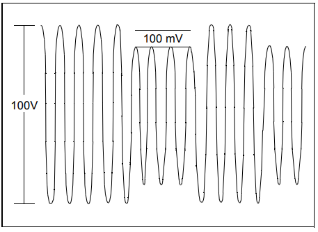
With this encoding, the tag changes the signal transmission level strictly in the middle of the transmission period of one bit. The transition from low to high level at these moments represents the state of logical "1", and the transition from high level to low represents the state of logical "0".

Real modulated signal captured on the reader coil.
Making an RFID emulator
Well, if you are still here and your head is not swollen from such calculations, then it’s time to make an RFID emulator, from just two parts. In this simplicity lies genius. I assembled the device by borrowing the idea and code from Micah Dowty, photos are mine.

This miniature cockroach may well emulate the
Project Website label . The code is very interesting, one might say ingenious and concise (assembler is used). Let's look at it in detail. We'll sort it out. You can view the code here.
First, let’s figure out how this thing actually functions, although by definition it shouldn’t work, since it contradicts the usual microcontroller connection diagram. The device diagram is taken from the source code.

An inductor of about 1 μH and an ATtiny85 microcontroller
This, ladies and gentlemen, is real Hacking, when the level of understanding of the operating features of the equipment allows you to create technical solutions that go beyond the scope specified by the manufacturer! And it works, I tested it personally. This is the true meaning of the word “hacker”, it is not about hacking and theft.
Looking ahead, I will say that this coil is not enough for normal operation, and yet I had to make a normal antenna, hang power supply capacitors, and a resonant capacitor. But it’s quite suitable for demonstrating the principles of operation.
How does it work:
Before we go to analyze the code of this emulator, let's make it a normal antenna. My experiments with current circuitry revealed extreme instability of its operation. It only works very close to the reader and not always. Therefore, first I soldered a 0.1 uF capacitor to the controller's power legs, and then decided to make a real large oscillating circuit, like in a real tag.
- The coil actually powers the AVR microcontroller through the I/O pins. Each such controller has diodes on the input/output ports, which prevent the voltage at this pin from rising above the chip's supply voltage or from dropping the signal level below ground level. They are also used to prevent static breakdown, which leads to failure of the microcircuit. When the coil is brought close to the reader, an EMF equal to several volts is induced in it. When the voltage on the coil exceeds the controller supply voltage, then part of this energy is transferred through these limiting diodes to the power bus of the microcircuit. The result is that the microcontroller receives power. And the top and bottom of the sine wave are truncated, and the signal becomes more like a square wave.
- Power filtering using the capacitance of the AVR crystal. Usually, when installing a microcircuit, they put capacitors on the power supply to filter out interference (usually 0.1 µF ceramics and electrolyte in parallel). In this solution, filtering is carried out only by the internal capacitance of the power rails in the silicon chip of the AVR microcontroller. It is small, but even it is enough for stable power supply and operation, when powered by pulses with a frequency of 125 kHz!
- Operation is carried out at very low voltage. The ATtiny85 microcontroller is designed to operate at voltages as low as 2.5 V. There is a version with an extended voltage range up to 1.8 V. At these voltages, regular AVR clock generators do not work, but this can be avoided by using the following hack...
- The inductor is used not only to power the microcircuit, but also to clock the microcontroller! We said above that we get a square wave, which remains after the limiting diodes have taken some energy. This waveform is the Clock input of our microcontroller! And all the code runs at 125 kHz, synchronous with the carrier frequency of the RFID reader. This is brilliant, guys!
- Firmware? At such low speeds, the chip's firmware is more like a series of I/O operations performed synchronously with each carrier clock cycle. But there are a lot of extra cycles left. In the EM4102 protocol, you can potentially do some useful work with 32 clock cycles between each bit. However, with the HID protocol, you need to output an FSK edge every 4 clock cycles. As a result, the firmware on the RFID tag is extremely stupid. The "source code" is really just a bunch of fancy assembly language macros that convert the RFID tag code into a long sequence of I/O instructions.

The first modification is a 0.1 µF capacitor for power supply
Creating an Antenna
There are no tricks in creating a coil antenna, but you still need to read the documentation and understand the physics of the process... It’s not difficult, and even a schoolboy can do it, it just takes a little patience and perseverance.
Assembling and setting up the antenna is very simple, just like in the picture from [1] .

To calculate the antenna, you need to remember a little theory. We need to make an oscillating circuit that will be tuned to a frequency of 125 kHz. Let's open the course on Theoretical Fundamentals of Electrical Engineering and read what an oscillatory circuit is:
An oscillating circuit is an electrical circuit containing an inductor and a capacitor in which electrical oscillations can be excited.

Parallel oscillatory circuit
If we leave all the mathematics and get to the point, the oscillatory circuit has such a parameter as the resonant frequency, which is determined by the formula.

Where f is the oscillation frequency, L is the inductance of the coil, C is the capacitance of the capacitor.
In this case, we have a fixed parameter - frequency, and we can play with capacitance and inductance. In order to calculate the coil, we will use the document [2] . Anyone who is somehow planning to make antennas for RFID tags (of any frequency) must familiarize themselves with it!
Many craftsmen, both for readers and emulators (the essence is not important), make round coils. They are easier to count and make, but they have a significant drawback - their linear dimensions are larger than the card. I want to make an inductor in the shape of a rectangle, with linear dimensions smaller than the dimensions of a standard card and so that the resulting device is the size of a standard RFID card. As a result, I choose the size of the future inductor coil that is almost the same as in the real mark, that is, approximately 70x40 mm . If the capacitor is chosen to be 10 nF, then the inductance of the coil (from the formula above) should be 162 μH. Now let's look at the documentation for calculating a rectangular coil. To wind the coil I chose a wire with a cross section of 0.2 mm. As a result, we open the corresponding section of the documentation, and the following glorious formula appears to our eyes.

As you can see, the parameters of the thickness and width of the coil are unknown and changeable (they depend on the wire thickness of 0.2 mm), but general estimates gave me a figure of 42 turns. It would be possible to do several iterations and make a very precise calculation, but in our individual case, it will do.
After that, it is necessary to make a 70x40 mm frame for winding the coil. I made it from PCB and wound a coil on it.

Textolite frame


Winding and finished coil
Unfortunately, I don’t have an inductance meter, so I had to proceed further using the scientific method. Since I probably made a mistake in the calculations and in the number of turns when I wound the coil, since I did them approximately and by eye, I decided to select the resonant capacitance manually. To do this, I secured the coil on the card reader, stuck its ends into the breadboard (“mattress with holes”), then began to connect the capacitances one by one, while recording the signal on the oscilloscope.

Let's start selecting a resonant capacitor.
First, I checked a capacitor with a capacity of 10 nF, which should be resonant. But the amplitude of the signal immediately dropped compared to an empty coil. Then I took a capacitor of a lower value. And so I went through the capacitors until I caught the resonance. Thus, the resonant capacitance of the capacitor was 3.2 nF.

Signal without capacitor, empty coil

10 nF signal

1 nF, 2 nF

3 nF, 4 nF, 2.2 nF

3.2 nF
It can be seen that I tried different options, and it was clear that the maximum lies somewhere between 3 and 4 nF and the result was a 3.2 nF capacitor (consisting of two capacitors in parallel). That's it, our coil is ready for further experiments.
In general, I would like to note that the coil can be made in the form of tracks on a printed circuit board, and for a small series of products it is worth doing so. Here is an example of such a board, specifically at 125 kHz from Alexander Guthmann . Unfortunately, the site is practically dead, and the author has not been in touch for a long time, so we are content with only my photos. If anyone can help me find it, I would be grateful! I don't know what happened to him.

Thus, making an emulator directly in the form of a printed circuit board is no problem. I think if you have the manual [2] , you will be able to calculate this yourself, since a fourteen-year-old German schoolboy could do it.
Let's go through the code
Let's take a quick look at the code, which can be viewed here. There is an example of emulation of two types of cards; I will only analyze EM4102.
First of all, as the code says, when flashing the microcontroller, we need to flash the fuse bits to the value lfuse to 0xC0 : so that the controller is clocked from an external oscillator. Please note that any re-flashing of the controller will involve the fact that it will need to be clocked from an external source, since we are installing fuse bits with generation from an external generator!
All code is based on macros. Let me remind you what macros are - they are programs that prepare code for compilation. Our program consists of just a few assembly instructions: rjmp, call (2 clock cycles), nop, ldi, out and ret (all 1 clock cycle)! That's it, all the rest of the code is formed by macros depending on the serial number macro (define). The peculiarity of the work is that we have quite a few clock cycles for normal operation. Try to do something in 32 clock cycles, considering that jump instructions in the AVR controller take 2 clock cycles. Therefore, all code is generated by macros depending on the ID card.
Code:
#define FORMAT_IS_EM4102
#define EM4102_MFR_ID        0x12
#define EM4102_UNIQUE_ID    0x3456789A
Using defines, we set what type of card we are emulating and set ID cards. This is the main macro, on the basis of which the rest of the code is generated. And, tadam, His Majesty macros.
Code:
.macro    delay cycles
    .if \cycles > 1
    rjmp    .+0
    delay    (\cycles - 2)
    .elseif \cycles > 0
    nop
    delay    (\cycles - 1)
    .endif
    .endm
Delay macro takes as input the number of delay cycles. A fairly obvious recursive macro, it delays using the nop command (no operation, 1 clock cycle) and the rjmp .+0 command (jump to the next line, 2 clock cycles). By combining these commands with each other, you can make a delay of the desired length in clock cycles. In fact, the code does nothing but waste machine time.
If you are still thinking, then I will completely rape your brain, but the code is so brilliant that you will have to be patient.
Recursive Manchester encoding macro.
Code:
.macro    manchester bit, count=1
    .if        \count
    manchester (\bit >> 1), (\count - 1)
    .if        \bit & 1
    baseband_1
    baseband_0
    .else
    baseband_0
    baseband_1
    .endif
    .endif
    .endm

    .macro    stop_bit
    baseband_0
    baseband_1_last
    .endm
Actually, this is where all the logic comes into play. Receives a bit mask and a bit counter as input. If the counter is not zero, then we call ourselves again, decrementing the counter (recursive macro, yeah). Further in the body itself there are calls to the macros baseband_0, baseband_1 and baseband_1_last. Depending on which bit we have “1” or “0”, we modulate the Manchester code signal from zero to one or from one to zero.
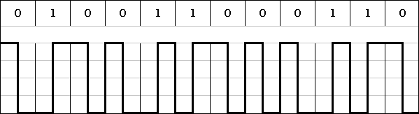
Remember above, I gave a table in the article about how the contents of the card are encoded, where the parity bits go, and the stop bits at the end. So, our task now is to encode ID tags using this method; for this we have two macros.
Code:
#define ROW_PARITY(n)  ( (((n) & 0xF) << 1) | \
                         (((n) ^ ((n) >> 1) ^ ((n) >> 2) ^ ((n) >> 3)) & 1) )

#define COLUMN_PARITY  ( (EM4102_MFR_ID >> 4) ^        \
                         (EM4102_MFR_ID) ^             \
                         (EM4102_UNIQUE_ID >> 28) ^    \
                         (EM4102_UNIQUE_ID >> 24) ^    \
                         (EM4102_UNIQUE_ID >> 20) ^    \
                         (EM4102_UNIQUE_ID >> 16) ^    \
                         (EM4102_UNIQUE_ID >> 12) ^    \
                         (EM4102_UNIQUE_ID >> 8) ^     \
                         (EM4102_UNIQUE_ID >> 4) ^     \
                         (EM4102_UNIQUE_ID) )
ROW_PARITY - calculation of the parity bit in a string of four bits, COLUMN_PARITY - calculation of the checksum of the entire package.
All our work logic is described in a macro in .main
Code:
header
        manchester    ROW_PARITY(EM4102_MFR_ID >> 4), 5
        manchester    ROW_PARITY(EM4102_MFR_ID >> 0), 5
        manchester    ROW_PARITY(EM4102_UNIQUE_ID >> 28), 5
        manchester    ROW_PARITY(EM4102_UNIQUE_ID >> 24), 5
        manchester    ROW_PARITY(EM4102_UNIQUE_ID >> 20), 5
        manchester    ROW_PARITY(EM4102_UNIQUE_ID >> 16), 5
        manchester    ROW_PARITY(EM4102_UNIQUE_ID >> 12), 5
        manchester    ROW_PARITY(EM4102_UNIQUE_ID >> 8), 5
        manchester    ROW_PARITY(EM4102_UNIQUE_ID >> 4), 5
        manchester    ROW_PARITY(EM4102_UNIQUE_ID >> 0), 5
        manchester    COLUMN_PARITY, 4
        stop_bit
Well, that is, we accurately transmit the 9 header bits, then Manchester coding, calculating the parity bit for every 4 bits, and at the end the checksum and stop bit.
It remains to figure out what baseband is. For this, we use another wrapper macros (how many are possible, eh?).
Code:
 .macro baseband_0
        rcall    baseband30_0
        rjmp    .+0
        .endm

        .macro baseband_1
        rcall    baseband30_1
        rjmp    .+0
        .endm

        .macro baseband_1_last
        rcall    baseband30_1
        rjmp    main
        .endm

        .macro header
        manchester 0x1FF, 9
        .endm
Baseband* macros - execute assembly code: call the appropriate functions, and then switch to another command. The baseband_1_last macro is similar to the baseband_1 macro, except that it makes an unconditional jump not to the command below, but to the beginning of the main function. The header macro is used to display a header of nine bits of the same type equal to one, and calls the Manchester macro with the transmission of the number and number of transmitted bits.
The last thing left to look at is the baseband30_0 and baseband30_1 functions. They are described by the following code.
Code:
baseband30_0:
        ldi    r16, OUT_PINS        // 1
        rjmp    baseband30        // 2

        /*
         * Emit a 1 at the baseband layer.
         * Takes a total of 30 clock cycles, including call overhead.
         */
baseband30_1:
        ldi    r16, 0            // 1
        rjmp    baseband30        // 2

        /*
         * Internal routine for baseband32_0 and _1. Must use
         * a total of 24 clock cycles. (32 - 1 ldi - 2 rjmp - 3 rcall)
         */
baseband30:
        out    _SFR_IO_ADDR(DDRB), r16        // 1
        delay    19                // 19
        ret                    // 4
Depending on which function is called baseband30_0 or baseband30_1, the value of what should be on the I/O pin is written to register r16: 1 or 0. After this, there is an unconditional transition to baseband30, an output is carried out and a delay of 19 clock cycles, after which there is a return.
The greatest magic of this code is that it is calculated exactly to each clock cycle; each clock cycle of the Manchester code transmission takes exactly as many periods as allowed by the standard, namely 32 processor cycles! This is fantastically brilliant, you have to remember how many clock cycles each command takes.
Let's compile it quickly and see how it looks, how all these macros unfold. We compile with the make command (after installing avr-gcc) and disassemble the resulting elf file
Code:
00000000 __vectors:
   0:    0e c0           rjmp    .+28         ; 0x1e __ctors_end
2: 15 c0 rjmp .+42 ; 0x2e __bad_interruptFirst we have interrupt vectors, but we are only interested in the first jump. Since the remaining vectors do not lead anywhere.
Code:
0000001e __ctors_end:
  1e:    11 24           eor    r1, r1
  20:    1f be           out    0x3f, r1    ; 63
  22:    cf e5           ldi    r28, 0x5F    ; 95
  24:    d2 e0           ldi    r29, 0x02    ; 2
  26:    de bf           out    0x3e, r29    ; 62
  28:    cd bf           out    0x3d, r28    ; 61
  2a:    02 d0           rcall    .+4          ; 0x30 main
  2c:    11 c1           rjmp    .+546        ; 0x250 _exit
Here we configure the I/O ports and call the main function. A main consists of an insane number of baseband30* and jump function calls (this is how our hellish macro circus unfolded).
Code:
00000030 main:
  30:    01 d1           rcall    .+514        ; 0x234 baseband30_1
  32:    00 c0           rjmp    .+0          ; 0x34 main+0x4
  34:    fd d0           rcall    .+506        ; 0x230 baseband30_0
  36:    00 c0           rjmp    .+0          ; 0x38 main+0x8
  38:    fd d0           rcall    .+506        ; 0x234 baseband30_1
  3a:    00 c0           rjmp    .+0          ; 0x3c main+0xc
  3c:    f9 d0           rcall    .+498        ; 0x230 baseband30_0
  3e:    00 c0           rjmp    .+0          ; 0x40 main+0x10
  40:    f9 d0           rcall    .+498        ; 0x234 baseband30_1
  42:    00 c0           rjmp    .+0          ; 0x44 main+0x14
  44:    f5 d0           rcall    .+490        ; 0x230 baseband30_0
  46:    00 c0           rjmp    .+0          ; 0x48 main+0x18
  48:    f5 d0           rcall    .+490        ; 0x234 baseband30_1
  4a:    00 c0           rjmp    .+0          ; 0x4c main+0x1c
  4c:    f1 d0           rcall    .+482        ; 0x230 baseband30_0
...
 22e:    00 cf           rjmp    .-512        ; 0x30 main

And so on... until we jump back to main.

Well, let's see what our baseband module looks like.

00000230 baseband30_0:
 230:    08 e1           ldi    r16, 0x18    ; 24
 232:    02 c0           rjmp    .+4          ; 0x238 baseband30

00000234 baseband30_1:
 234:    00 e0           ldi    r16, 0x00    ; 0
 236:    00 c0           rjmp    .+0          ; 0x238 baseband30

00000238 baseband30:
 238:    07 bb           out    0x17, r16    ; 23
 23a:    00 c0           rjmp    .+0          ; 0x23c baseband30+0x4
 23c:    00 c0           rjmp    .+0          ; 0x23e baseband30+0x6
 23e:    00 c0           rjmp    .+0          ; 0x240 baseband30+0x8
 240:    00 c0           rjmp    .+0          ; 0x242 baseband30+0xa
 242:    00 c0           rjmp    .+0          ; 0x244 baseband30+0xc
 244:    00 c0           rjmp    .+0          ; 0x246 baseband30+0xe
 246:    00 c0           rjmp    .+0          ; 0x248 baseband30+0x10
 248:    00 c0           rjmp    .+0          ; 0x24a baseband30+0x12
 24a:    00 c0           rjmp    .+0          ; 0x24c baseband30+0x14
 24c:    00 00           nop
 24e:    08 95           ret
At the end you can see how delay has expanded into a list of jump and nop for delay. This is such beautiful magic.
Well, we figured out the code. Collect the leaked brain from the ears, let's move on to the tests.
Tests
We will apply all the knowledge gained and conduct tests. We compile the firmware, flash the controller, not forgetting to set the Fuse bits correctly.

Scarf for firmware
We connect our oscillatory circuit and test it on a real industrial reader, no half measures, fair combat conditions.

Test stand
And, lo and behold! It works, is read correctly and gives the correct ID in the loop! Without external power, with operation only from the field. All that remains is to put it all in order and make a real RFID tag.

The final “laminated” version of the tag
Total
I can honestly admit that I didn’t fully believe that it would work. Power supply from the field, non-standard operating modes of the controller, operation strictly according to clock cycles, homemade inductor. Plus the work of RFID itself. And so, the seemingly worthless piece of work spreads over a couple of months of reading documentation and debriefing. But it works, and this thing is truly brilliant. So guys, these things are real hacking. Go for it!
Homework
Since you finally read this cool article, I wrote it, tried, did it, now it’s time for you to try to do something. There is a section in the emulator code that emulates HID Proximity cards with phase shift encoding. For fun and better learning, you should understand the HID standard and this coding. Send your solution in the comments. Good luck.
Bibliography
- AppNote 411 RFID Made Easy
- AN710 Antenna Circuit Design for RFID Applications
- When preparing this article, materials from the site priority1design.com were used