
Lord777
Professional
- Messages
- 2,577
- Reaction score
- 1,556
- Points
- 113
The ESP32-CAM is a handy little camera module with a lot of built-in power, and you can turn it into an inconspicuous spy camera to hide it in any room. There is only one problem: it is missing a USB port. It makes programming a bit more difficult, but with an ESP32-based board, FTDI programmer, and a few jumpers, you'll have a pre-programmed ESP32 Wi-Fi spy camera in no time. In this article, we will look at how to set up a Wi-Fi spy camera.
Content
1. Required details
2. Configuring the camera in the Arduino IDE
3. Open the default camera thumbnail
4. Configuring the sample sketch code
5. Connecting the ESP32-CAM
6. Uploading a sketch to ESP32-CAM
7. Find the power source for your ESP32-CAM
8. Connecting to the interface of your spy camera
9. Conclusion
Then, in the menu bar, go to Tools, then Whiteboard, and then Whiteboard Manager. In the search box, type "esp32", then install the latest version of "esp32 from Espressif Systems".
And you need to add // to the beginning of that, and then remove // from the beginning of that line:
So, this section in the code should now look like this:
Then we need to enter the SSID name and password for the Wi-Fi network that we want to connect the spy camera to. Find these two lines, then replace the asterisks with the name and password of your Wi-Fi network.
That's all for customizing the sketch. Click the compile button to compile it, and then you'll be ready to flash the ESP32-CAM program.
Here's what it should look like when finished:
Find the port that your ESP32-CAM is connected to in the Arduino IDE. First go to "Tools", select "Board", then select "AI Thinker ESP32-CAM" under "ESP32 Arduino" if you haven't already done this for some reason (you should have done it in step 2).
Then go to "Tools", select" Port", then change it to the correct one if it wasn't already selected automatically. Be especially careful when choosing the correct port for the ESP32-CAM, as you won't want to overwrite any other devices.
To transfer a Wi-Fi sketch to the ESP32-CAM, click the download button (right arrow in the upper-left corner). You'll see a bunch of things happen. As soon as the red text appears on the screen, you know that it is actually flashing. When this is done, you can open Serial Monitor with Control-Shift-M to make sure there were no crazy errors or shutdowns, and look for reboots.
After flashing the sketch in ESP32-CAM, find the board's IP address in Serial Monitor. You'll need this later.
Disconnect the ESP32-CAM from the breadboard, and then connect it to the D1 Mini Battery Shield, which will allow us to power the spy camera with a small LiPo battery. When connecting them, make sure that the 5V pins on both are properly aligned. Then connect the lithium-ion polymer battery to the shield using the two-pin JST-PH connector.
At the bottom of the menu, you'll see the "Face Recognition" and "Face Recognition" options that you can enable. At the moment, it only works with resolutions of 400 x 296 and below.
Click "Start Streaming" at the bottom to view the video stream. If you only have facial recognition enabled, you need to see a frame around someone's head to know that it works. When face recognition is enabled, it will do the same, but it will also name the person who will be the attacker first. You can click the "Register a Person" button to register them as non-violators
(c) https://cryptoworld.su/nastrojka-shpionskoj-kamery-wi-fi/
Content
1. Required details
2. Configuring the camera in the Arduino IDE
3. Open the default camera thumbnail
4. Configuring the sample sketch code
5. Connecting the ESP32-CAM
6. Uploading a sketch to ESP32-CAM
7. Find the power source for your ESP32-CAM
8. Connecting to the interface of your spy camera
9. Conclusion
Required details
These are the main things you need to continue this project:- ESP32-CAM Camera Module with FTDI USB to TTL Serial Converter
- D1 Mini Battery Shield with Charging Module
- 3.7 V Lithium polymer battery, 500 mAh
- Solderless breadboard
- Jumpers
- Mini USB Cable
- Arduino IDE Software
Configuring the camera in the Arduino IDE
In the Arduino IDE, go to" Arduino " or " File "in the menu bar, select" Settings", then click the window icon next to"Add-on Card Manager URLs". On a separate line, add the following URL, then click OK and OK again.Then, in the menu bar, go to Tools, then Whiteboard, and then Whiteboard Manager. In the search box, type "esp32", then install the latest version of "esp32 from Espressif Systems".
Open the default camera thumbnail
Go to "Tools" again in the menu bar, select "Board", then select "AI Thinker ESP32-CAM" under "ESP32 Arduino". After selecting this board, go to "File" - > "Examples" - > "ESP32" - > "Camera" - > "CameraWebServer". This will open the sketch and you will see the following code.
Code:
#include "esp_camera.h"
#include <WiFi.h>
//
// WARNING!!! PSRAM IC required for UXGA resolution and high JPEG quality
//            Ensure ESP32 Wrover Module or other board with PSRAM is selected
//            Partial images will be transmitted if image exceeds buffer size
//
// Select camera model
#define CAMERA_MODEL_WROVER_KIT // Has PSRAM
//#define CAMERA_MODEL_ESP_EYE // Has PSRAM
//#define CAMERA_MODEL_M5STACK_PSRAM // Has PSRAM
//#define CAMERA_MODEL_M5STACK_V2_PSRAM // M5Camera version B Has PSRAM
//#define CAMERA_MODEL_M5STACK_WIDE // Has PSRAM
//#define CAMERA_MODEL_M5STACK_ESP32CAM // No PSRAM
//#define CAMERA_MODEL_AI_THINKER // Has PSRAM
//#define CAMERA_MODEL_TTGO_T_JOURNAL // No PSRAM
#include "camera_pins.h"
const char* ssid = "*********";
const char* password = "*********";

void startCameraServer();

void setup() {
Serial.begin(115200);
Serial.setDebugOutput(true);
Serial.println();

camera_config_t config;
config.ledc_channel = LEDC_CHANNEL_0;
config.ledc_timer = LEDC_TIMER_0;
config.pin_d0 = Y2_GPIO_NUM;
config.pin_d1 = Y3_GPIO_NUM;
config.pin_d2 = Y4_GPIO_NUM;
config.pin_d3 = Y5_GPIO_NUM;
config.pin_d4 = Y6_GPIO_NUM;
config.pin_d5 = Y7_GPIO_NUM;
config.pin_d6 = Y8_GPIO_NUM;
config.pin_d7 = Y9_GPIO_NUM;
config.pin_xclk = XCLK_GPIO_NUM;
config.pin_pclk = PCLK_GPIO_NUM;
config.pin_vsync = VSYNC_GPIO_NUM;
config.pin_href = HREF_GPIO_NUM;
config.pin_sscb_sda = SIOD_GPIO_NUM;
config.pin_sscb_scl = SIOC_GPIO_NUM;
config.pin_pwdn = PWDN_GPIO_NUM;
config.pin_reset = RESET_GPIO_NUM;
config.xclk_freq_hz = 20000000;
config.pixel_format = PIXFORMAT_JPEG;

// if PSRAM IC present, init with UXGA resolution and higher JPEG quality
//                      for larger pre-allocated frame buffer.
if(psramFound()){
config.frame_size = FRAMESIZE_UXGA;
config.jpeg_quality = 10;
config.fb_count = 2;
} else {
config.frame_size = FRAMESIZE_SVGA;
config.jpeg_quality = 12;
config.fb_count = 1;
}

#if defined(CAMERA_MODEL_ESP_EYE)
pinMode(13, INPUT_PULLUP);
pinMode(14, INPUT_PULLUP);
#endif

// camera init
esp_err_t err = esp_camera_init(&config);
if (err != ESP_OK) {
Serial.printf("Camera init failed with error 0x%x", err);
return;
}

sensor_t * s = esp_camera_sensor_get();
// initial sensors are flipped vertically and colors are a bit saturated
if (s->id.PID == OV3660_PID) {
s->set_vflip(s, 1); // flip it back
s->set_brightness(s, 1); // up the brightness just a bit
s->set_saturation(s, -2); // lower the saturation
}
// drop down frame size for higher initial frame rate
s->set_framesize(s, FRAMESIZE_QVGA);

#if defined(CAMERA_MODEL_M5STACK_WIDE) || defined(CAMERA_MODEL_M5STACK_ESP32CAM)
s->set_vflip(s, 1);
s->set_hmirror(s, 1);
#endif

WiFi.begin(ssid, password);

while (WiFi.status() != WL_CONNECTED) {
delay(500);
Serial.print(".");
}
Serial.println("");
Serial.println("WiFi connected");

startCameraServer();

Serial.print("Camera Ready! Use 'http://");
Serial.print(WiFi.localIP());
Serial.println("' to connect");
}

void loop() {
// put your main code here, to run repeatedly:
delay(10000);
}
Configuring the sample sketch code
In the default CameraWebServer sketch, we need to make sure that our AI Thinker board is selected, and not another board. At the moment, the next board will not be commented out:
Code:
#define CAMERA_MODEL_WROVER_KIT // Has PSRAMAnd you need to add // to the beginning of that, and then remove // from the beginning of that line:
Code:
//#define CAMERA_MODEL_AI_THINKER // Has PSRAMSo, this section in the code should now look like this:
Code:
// Select camera model
//#define CAMERA_MODEL_WROVER_KIT // Has PSRAM
//#define CAMERA_MODEL_ESP_EYE // Has PSRAM
//#define CAMERA_MODEL_M5STACK_PSRAM // Has PSRAM
//#define CAMERA_MODEL_M5STACK_V2_PSRAM // M5Camera version B Has PSRAM
//#define CAMERA_MODEL_M5STACK_WIDE // Has PSRAM
//#define CAMERA_MODEL_M5STACK_ESP32CAM // No PSRAM
#define CAMERA_MODEL_AI_THINKER // Has PSRAM
//#define CAMERA_MODEL_TTGO_T_JOURNAL // No PSRAM
Then we need to enter the SSID name and password for the Wi-Fi network that we want to connect the spy camera to. Find these two lines, then replace the asterisks with the name and password of your Wi-Fi network.
Code:
const char* ssid = "*********";
const char* password = "*********";
That's all for customizing the sketch. Click the compile button to compile it, and then you'll be ready to flash the ESP32-CAM program.
Connecting an ESP32-CAM
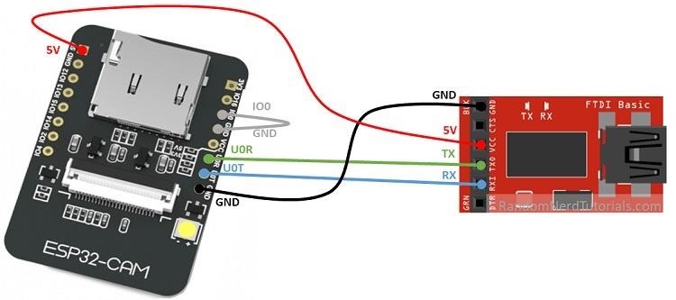
With your FTDI programmer and ESP32-CAM module, use jumpers with or without a breadboard to connect the FTDI programmer and the ESP32-CAM module together.- Connect the GND on the FTDI to the GND (via U0T) on the ESP32-CAM.
- Connect the 5V on the FTDI to the 5V on the ESP32-CAM.
- Connect the TX on the FTDI to the U03 on the ESP32-CAM.
- Connect RX on the FTDI to U0T on the ESP32-CAM.
- Connect the I00 on the ESP32-CAM to the GND next to it.
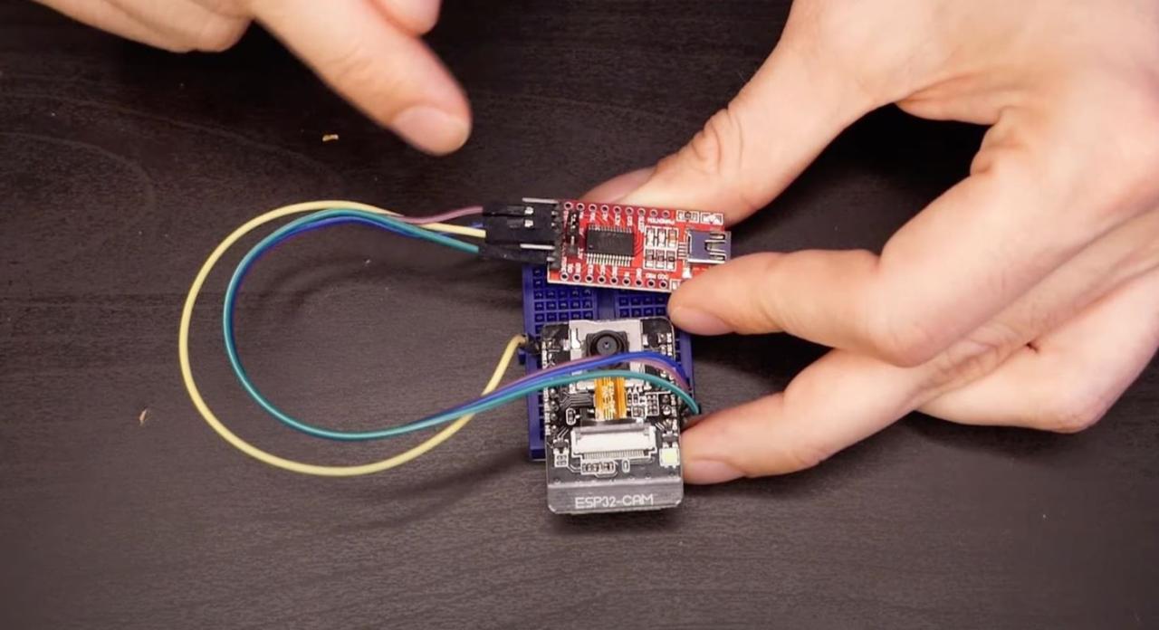
Here's what it should look like when finished:
Uploading a sketch to ESP32-CAM
Once all the jumpers are installed, you can connect a Mini-USB cable with a regular USB connector to your computer, and then download the sketch.Find the port that your ESP32-CAM is connected to in the Arduino IDE. First go to "Tools", select "Board", then select "AI Thinker ESP32-CAM" under "ESP32 Arduino" if you haven't already done this for some reason (you should have done it in step 2).
Then go to "Tools", select" Port", then change it to the correct one if it wasn't already selected automatically. Be especially careful when choosing the correct port for the ESP32-CAM, as you won't want to overwrite any other devices.
To transfer a Wi-Fi sketch to the ESP32-CAM, click the download button (right arrow in the upper-left corner). You'll see a bunch of things happen. As soon as the red text appears on the screen, you know that it is actually flashing. When this is done, you can open Serial Monitor with Control-Shift-M to make sure there were no crazy errors or shutdowns, and look for reboots.
After flashing the sketch in ESP32-CAM, find the board's IP address in Serial Monitor. You'll need this later.
Find the power source for your ESP32-CAM
Now that your ESP32-CAM is programmed, you can disable the FTDI programmer; you will only need this if you need to update the code on your spy cam later. You can also connect a permanent power supply to the FTDI programmer while it's still connected to the ESP32-CAM if you want to power up the camera that way, but since we want it to be a spy camera, the battery would be much better.Disconnect the ESP32-CAM from the breadboard, and then connect it to the D1 Mini Battery Shield, which will allow us to power the spy camera with a small LiPo battery. When connecting them, make sure that the 5V pins on both are properly aligned. Then connect the lithium-ion polymer battery to the shield using the two-pin JST-PH connector.
Connecting to the interface of your spy camera
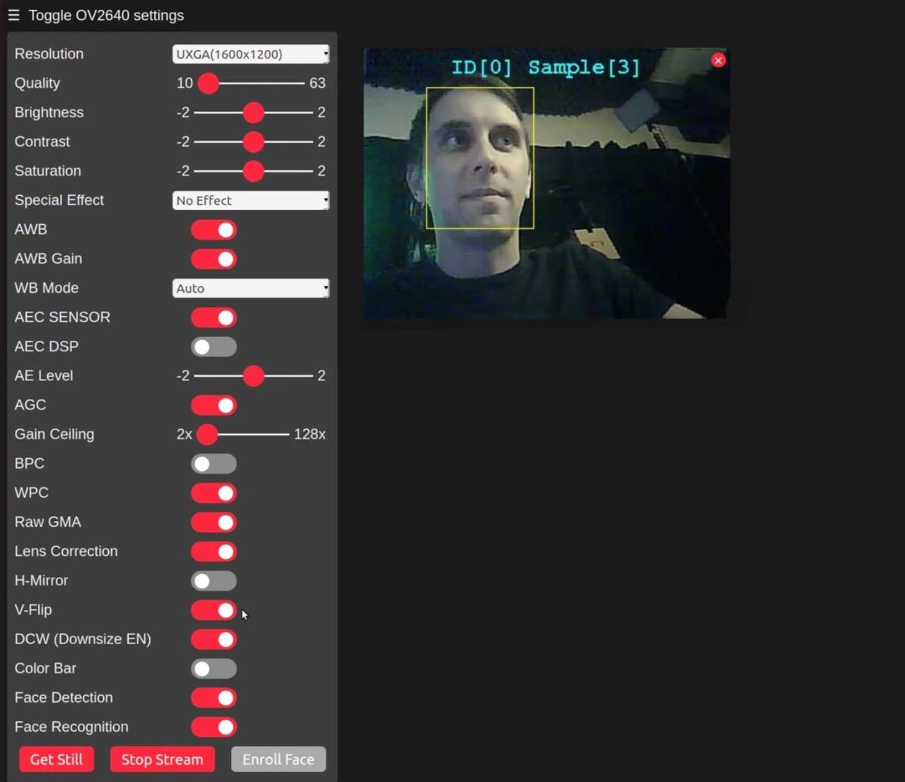
In the browser window, open the ESP32-CAM IP address that you found earlier on the same Wi-Fi network. This will give you access to the spy camera settings. You can change the resolution, video quality, brightness, contrast, and saturation until you get the desired image, as well as add special effects and adjust other settings.At the bottom of the menu, you'll see the "Face Recognition" and "Face Recognition" options that you can enable. At the moment, it only works with resolutions of 400 x 296 and below.
Click "Start Streaming" at the bottom to view the video stream. If you only have facial recognition enabled, you need to see a frame around someone's head to know that it works. When face recognition is enabled, it will do the same, but it will also name the person who will be the attacker first. You can click the "Register a Person" button to register them as non-violators
Conclusion
These boards can get very hot, so depending on your battery and how long you use the camera, it may not work or turn off. If this happens, consider getting a proper radiator to dissipate heat and keep things cool. The more things you add to the spy camera, the harder it will be to hide it in an inconspicuous place, so keep this in mind.(c) https://cryptoworld.su/nastrojka-shpionskoj-kamery-wi-fi/