
Tomcat
Professional
- Messages
- 2,695
- Reaction score
- 1,064
- Points
- 113
Contents of this part
- What is WebRTC?
- Why learn WebRTC?
- The WebRTC protocol is a collection of other technologies
- Signaling: how peers find each other
- Connecting and displaying NAT using STUN/TURN
- Securing the Data Link Using DTLS and SRTP
- Communication between peers via RTP and SCTP
- WebRTC - a collection of protocols
- How does WebRTC (API) work?
- Signaling
- How does the alarm work?
- What is Session Description Protocol (SDP)?
- Studying SDP
- WebRTC uses only some SDP keys
- Media descriptions in the session description
- Full example
- How SDP and WebRTC work together
- What are suggestions and answers?
- Transceivers
- SDP values used in WebRTC
- Example of a WebRTC session description
- Connection
- How it works?
- Real World Constraints
- Different networks
- Protocol Limitations
- Firewall Rules
- NAT Mapping
- Creating a NAT Mapping
- Options for creating a NAT mapping
- NAT Mapping Filtering Options
- Updating the NAT Mapping
- STUN
- Protocol structure
- Creating a NAT Mapping
- NAT Type Determination
- TURN
- Lifecycle of TURN
- Using TURN
- ICE
- Creating an ICE Agent
- Candidate Gathering
- Connection checks
- Selection of candidates
- Reboot
What is WebRTC?
WebRTC(Web Real-Time Communication - real-time communication) is an API (Application Programming Interface) and protocol. A protocol WebRTCis a set of rules that allows two agents WebRTC (browsers) to conduct bi-directional, secure communication in real time. WebRTC APIallows developers to use the WebRTC. WebRTC APIcurrently only defined for JavaScript.
You may already be aware of another pair with similar interaction between HTTP and Fetch API . In our case, the protocol WebRTCis HTTP, and WebRTC APIis Fetch API.
The protocol is maintained by the IETF rtcwebWebRTC working group . documented in the W3C as webrtc . WebRTC API
Why learn WebRTC?
If you try to briefly describe the features WebRTC, you will get the following list. Moreover, it is not exhaustive, these are just examples of interesting characteristics that you will encounter while studying WebRTC. Don't worry if you are not familiar with some of the terms, they will all be covered below:
- Open standard.
- Different implementations.
- Availability in browsers.
- Mandatory encryption.
- NAT mapping (NAT Traversal).
- Repurposing existing technologies.
- Congestion control.
- Low latency (at the level of fractions of a second, sub-second latency).
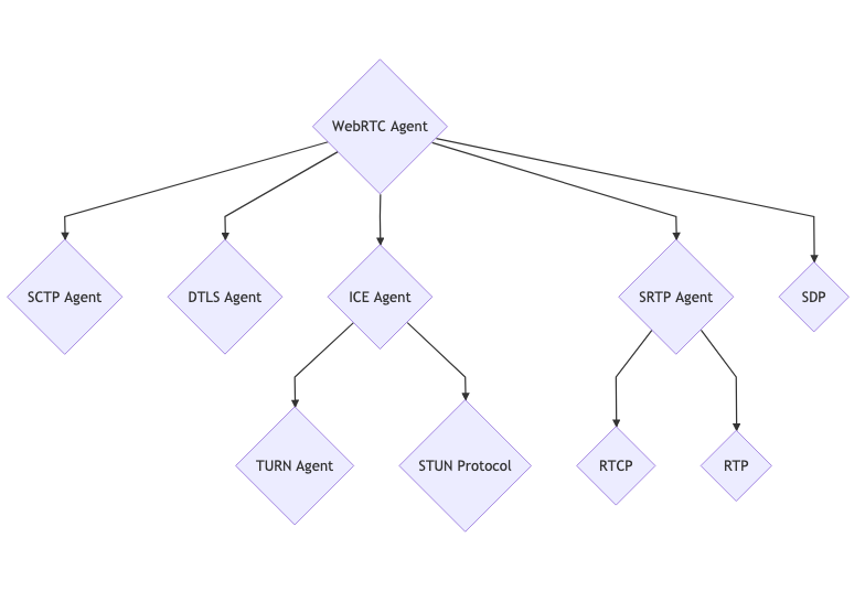
The WebRTC protocol is a collection of other technologies
In the process of establishing a connection using WebRTC4 stages:
- Signaling.
- Connection (connection establishment).
- Security.
- Communication (interaction).
Transitions between stages occur sequentially. A prerequisite for starting the next stage is the successful completion of the previous one.
An interesting fact about this WebRTCis that each stage consists of a large number of other protocols. WebRTCMany existing technologies were combined to create it . In this sense WebRTC, it is a combination and configuration of well-known technologies that emerged in the early 2000s.
Each of the listed 4 stages is devoted to a separate section, but first let's look at them at the highest level.
Since the stages depend on each other, this will make it easier to explain and understand the purpose of each of them later.
Signaling: how peers find each other
When launched WebRTC, the agent does not know with whom and about what the communication will take place. And it is signaling that gives us transparency. This is the first stage and its purpose is to prepare a call so that two agents WebRTCcan begin communication.
Signaling is carried out using an existing protocol SDP (Session Description Protocol). Let us remember that SDPthis is a text protocol. Each message SDPconsists of several key/value pairs and contains a list of "media sections". SDPexchanged between agents WebRTCcontains the following information:
- IP and ports through which you can access the agent (candidates);
- how many audio and video tracks the agent wants to send;
- what audio and video codecs are supported by each agent;
- values used during connection process ( uFrag/uPwd);
- values used for security (certificate fingerprint).
Please note that signaling usually occurs outside WebRTC; WebRTC, usually not used to transmit signaling messages. Technologies such as REST SDP endpoints, web sockets, or authentication proxies can be used for communication between connected peers.
Connecting and displaying NAT using STUN/TURN
During the signaling process, agents WebRTCreceive enough information to attempt a connection. For this, another technology called ICE.
ICE(Interactive Connectivity Establishment) is another protocol that predates the advent of WebRTC. ICEallows you to establish a connection between two agents. Agents can be located on the same (local) network or in different parts of the world. ICEis a solution for establishing a direct connection without a central server.
The real magic is "NAT mapping" and servers STUN/TURN. And that's all you need to communicate with an agent ICElocated on a different subnet.
After successful connection, ICE WebRTCit begins to install an encrypted transport channel. It is used to transmit audio, video and other data.
Securing the Data Link Using DTLS and SRTP
Once we have established a bidirectional communication channel (using ICE), we need to make this channel secure. This is done using two protocols, also developed long before the advent of WebRTC. The first protocol is DTLS (Datagram Transport Layer Security ), which is simply TLS on top of UDP. TLSis a cryptographic protocol that is used for secure communication over HTTPS. The second protocol is SRTP (Secure Real-time Transport Protocol - used for secure real-time data transfer).
First WebRTCperforms a handshake usingDTLS the connection ICE. Unlike HTTPS, WebRTCit does not use a central authority to verify certificates. Instead, WebRTCit verifies that the certificate passed through DTLSmatches the fingerprint (we'll talk about this in detail in the security section) passed through the signaling process. Later DTLS-подключениеit is used to transmit messages via DataChannel(data communication channel).
For audio/video transmission, another protocol called RTP(Real-time Transport Protocol) is used. Packets transmitted over RTP, are protected using SRTP. The session SRTPbegins by retrieving the keys from the established session DTLS.
Congratulations! If the previous steps have completed successfully, we have bidirectional and secure communication. If the connection between agents WebRTCis stable, you can begin exchanging data. Unfortunately, in the real world we are constantly faced with packet loss and limited bandwidth, which we will discuss in the next section.
Communication between peers via RTP and SCTP
So, we have established a secure bidirectional connection between two agents WebRTCand we are finally starting to communicate! For this, two protocols are used: SCTP RTP (Stream Control Transmission Protocol). is used to transmit media encrypted with , and is needed to send and receive messages via , encrypted with .RTPSRTPSCTPDataChannelDTLS
RTPis quite minimalistic, but it provides everything you need for real-time streaming. Flexibility RTPallows developers to address latency, data loss, and congestion issues in a variety of ways.
The last protocol in the stack is SCTP. It provides many settings related to message delivery. We, for example, may sacrifice reliability and the correct order of delivery of data packets in favor of low delivery latency. This is what is critical for real-time communication.
WebRTC - a collection of protocols
At first glance WebRTCit may seem over-engineered. But we can forgive him for this, since with his help we can solve a large number of problems. The genius WebRTClies in his modesty: he does not try to solve all the problems himself. Instead, it combines many existing specialized technologies into a single whole.
This allows you to explore and study each part separately. A very appropriate comparison WebRTCis that of an orchestrator for a large number of other protocols.
How does WebRTC (API) work?
In this section we will talk about how the protocol WebRTCis implemented in JavaScript API. This is not a detailed overview, but merely an attempt to paint a general picture of what happens in real-time communication.
new RTCPeerConnection
RTCPeerConnection— “WebRTC session” of the top level. It combines all the protocols mentioned above. All necessary subsystems are being prepared, but nothing is happening yet.
addTrack
addTrackcreates a new data stream (stream) RTP. A random synchronization source is generated for this thread SSRC. The stream is inside the Session Description SDP(in the media section) generated by createOffer. Each call addTrackcreates a new SSRCand media section.
Once installed SRTP-сессииand encrypted, these media packets begin to be transmitted through ICE.
createDataChannel
createDataChannelcreates a new one SCTP-потокin its absence. Disabled by default SCTP, it is enabled only when requested by either side of the data link.
Once installed DTLS-сессииand encrypted, these data packets begin to be transmitted via ICE.
createOffer
createOffergenerates a description of the local state of the session, transmitted to the remote (in the sense of “far away”, remote) peer.
The call createOfferdoes not change anything for the local peer.
setLocalDescription
setLocalDescriptioncommits the requested (made) changes. addTrack, createDataChanneland similar calls are temporary until called setLocalDescription. setLocalDescriptioncalled with the value generated by createOffer.
setRemoteDescription
setRemoteDescription– a way to inform the local agent about the status of remote candidates. This is signaling performed by JavaScript API.
After a call setRemoteDescriptionby both parties, the agents WebRTChave enough information to begin communication P2P(Peer-To-Peer - equal to equal).
addIceCandidate
addIceCandidateallows you WebRTC-агентуto add additional candidates ICEat any time. This interface sends the candidate ICEdirectly to the subsystem ICEand has no other effect on the overall connection.
ontrack
ontrackis a callback function that is called when received RTP-пакетаfrom a remote peer. Incoming packets are placed in a session description, which is passed to setRemoteDescription.
oniceconnectionstatechange
oniceconnectionstatechangeis a callback that is called when the agent's state changes ICE. This is how we receive notifications about connection establishment and completion.
onconnectionstatechange
onconnectionstatechangeis a combination of state ICEand DTLS. We can use this callback to receive notification of successful installation ICEand DTLS.
Signaling
At the time of its creation, the agent WebRTCknows nothing about the other peer. He has no idea with whom the connection will be established and what they will exchange. Signaling is preparation for making a call. After exchanging the necessary information, agents can communicate with each other directly.
The messages transmitted during the signaling process are simply text. Agents do not care how they are transmitted (what transport is used for this). Typically they are sent via websockets, but this is not required.
How it works?
WebRTCuses the protocol SDP. Through it, two agents exchange the state necessary to establish a connection. The protocol itself is easy to read. The difficulty comes when examining the values generated by WebRTC.
This protocol is not specific to WebRTC. First, we will consider SDPin isolation from WebRTC, and then its application in WebRTC.
What is Session Description Protocol (SDP)?
The Session Description Protocol is defined in RFC 8866. It consists of key/value pairs. Each pair is on a separate line. It is similar to an INI file. The session description consists of 0 or more media descriptions. You can think of a session description as an array of media descriptions.
A media description usually refers to a specific stream of media data. So if we want to describe a call containing 3 video streams and 2 audio streams, we will have 5 media descriptions.
Studying SDP
Each new line in the session description begins with one character - a key. Then comes the equal sign. Everything else (up to the new line) is the value.
SDPdefines all keys that are valid. Only letters of the Latin alphabet can be used for keys. Each key has a specific meaning.
Let's look at a small piece of the session description:
Code:
a=first-value
a=second-value
We have 2 lines and they both start with the key a. The value of the first line is first-value, and the second is second-value.
SDP keys used in WebRTC
Not all keys defined in SDPare used in WebRTC. Only keys that appear in the JavaScript Session Establishment Protocol JSEP, defined in RFC 8829, are used. Right now it is enough to understand the following 7 keys:
- v— version (version) 0;
- o— origin, a unique identifier useful for re-establishing a connection;
- s— session name ( -);
- t— timing ( 0 0);
- m— media description ( m=<media> <port> <proto> <fmt> ...);
- a— attribute, free text field. The most common key;
- c— connection information ( IN IP4 0.0.0.0).
Media descriptions in the session description
A session description can consist of an unlimited number of media descriptions.
A media description definition consists of a list of formats. These formats correspond to RTPRTP Payload Types. The codec is determined by an attribute with a value rtpmapin the session description. Each media description can consist of an unlimited number of attributes.
Let's look at one more piece of the session description:
Code:
v=0
m=audio 4000 RTP/AVP 111
a=rtpmap:111 OPUS/48000/2
m=video 4000 RTP/AVP 96
a=rtpmap:96 VP8/90000
a=my-sdp-value
We have two media descriptions: one describes audio with the format 111, the other describes video with the format 96. The first description contains one attribute. This attribute defines (maps) the payload type 111as Opus. The second description contains two attributes. The first attribute defines the payload type 96as VP8, the second one contains a custom value my-sdp-value.
Full example
The following example shows all the keys SDPused in WebRTC:
Code:
v=0
o=- 0 0 IN IP4 127.0.0.1
s=-
c=IN IP4 127.0.0.1
t=0 0
m=audio 4000 RTP/AVP 111
a=rtpmap:111 OPUS/48000/2
m=video 4002 RTP/AVP 96
a=rtpmap:96 VP8/90000- v, o, s, cand tare defined, but they do not affect the session WebRTC;
- we have two descriptions of media. One with type audio, the other - video;
- each description contains one attribute. It defines the details of a pipeline RTP.
How SDP and WebRTC work together
The next piece of the puzzle is understanding how to WebRTCuse SDP.
What are suggestions and answers?
WebRTCuses the offer/answer model. This means that if one agent "offers" to start communication, the other agent "responds" whether he wants to or not.
This allows the responder to reject unsupported codecs specified in the media descriptions. In this way, peers determine what data formats they will exchange.
Transceivers
Transceivers are WebRTCa concept specific to API. Their main task is to convert the "media description" into JavaScript API. Every media description becomes a transceiver. Each time a transceiver is created, a new media description is added to the local session description.
Each session description WebRTChas an attribute that determines the direction of data transfer (direction). This allows the agent to declare things like, "I'm going to send you this codec, but I don't want to receive anything back." Valid direction values are:
- send(sendonly, sending - sending);
- recv(recvonly, receiving - receiving);
- sendrecv(sending and receiving);
- inactive(inactive state).
SDP values used in WebRTC
Below is a list of some common session description attributes used by agents. Many of these values are controlled by subsystems that we haven't discussed yet (but will discuss soon).
group:BUNDLE
Bundling is the transmission of several types of traffic through one connection (often called “batching”, batching). Some implementations WebRTCallocate a separate connection for each media stream. Assembly is preferred.
fingerprint:sha-256
This is the hash of the certificate used by the peer for DTLS. Once the handshake is complete, DTLSwe compare the hash to the certificate to confirm that we are communicating with the person we expect.
setup:
Controls the behavior of the agent DTLS. Determines whether the agent is a client or a server after installation ICE. Possible values:
- setup:active— launch as a client DTLS;
- setup
 assive— launch as a server DTLS;
 - setup:actpass— we ask another agent WebRTCto make a choice.
ice-ufrag
The user fragment value for the agent ICE. Used for traffic authentication ICE.
ice-pwd
Agent password ICE. Used for traffic authentication ICE.
rtpmap
Used to define the relationship between a specific codec and payload type RTP. Payload types are dynamic, so for each call the initiator selects payload types for each codec.
fmtp
Defines additional payload type values. Can be used to configure video profile or encoding.
candidate
A candidate ICEreceived from an agent ICE. One of the addresses where the agent is available WebRTC.
ssrc
Defines a specific media stream track.
labelis the thread identifier. mslabel— identifier of a container that can contain multiple threads.
Example session description
Full session description generated by the client WebRTC:
Code:
v=0
o=- 3546004397921447048 1596742744 IN IP4 0.0.0.0
s=-
t=0 0
a=fingerprint:sha-256 0F:74:31:25:CB:A2:13:EC:28:6F:6D:2C:61:FF:5D:C2:BC:B9:DB:3D:98:14:8D:1A:BB:EA:33:0C:A4:60:A8:8E
a=group:BUNDLE 0 1
m=audio 9 UDP/TLS/RTP/SAVPF 111
c=IN IP4 0.0.0.0
a=setup:active
a=mid:0
a=ice-ufrag:CsxzEWmoKpJyscFj
a=ice-pwd:mktpbhgREmjEwUFSIJyPINPUhgDqJlSd
a=rtcp-mux
a=rtcp-rsize
a=rtpmap:111 opus/48000/2
a=fmtp:111 minptime=10;useinbandfec=1
a=ssrc:350842737 cname:yvKPspsHcYcwGFTw
a=ssrc:350842737 msid:yvKPspsHcYcwGFTw DfQnKjQQuwceLFdV
a=ssrc:350842737 mslabel:yvKPspsHcYcwGFTw
a=ssrc:350842737 label:DfQnKjQQuwceLFdV
a=msid:yvKPspsHcYcwGFTw DfQnKjQQuwceLFdV
a=sendrecv
a=candidate:foundation 1 udp 2130706431 192.168.1.1 53165 typ host generation 0
a=candidate:foundation 2 udp 2130706431 192.168.1.1 53165 typ host generation 0
a=candidate:foundation 1 udp 1694498815 1.2.3.4 57336 typ srflx raddr 0.0.0.0 rport 57336 generation 0
a=candidate:foundation 2 udp 1694498815 1.2.3.4 57336 typ srflx raddr 0.0.0.0 rport 57336 generation 0
a=end-of-candidates
m=video 9 UDP/TLS/RTP/SAVPF 96
c=IN IP4 0.0.0.0
a=setup:active
a=mid:1
a=ice-ufrag:CsxzEWmoKpJyscFj
a=ice-pwd:mktpbhgREmjEwUFSIJyPINPUhgDqJlSd
a=rtcp-mux
a=rtcp-rsize
a=rtpmap:96 VP8/90000
a=ssrc:2180035812 cname:XHbOTNRFnLtesHwJ
a=ssrc:2180035812 msid:XHbOTNRFnLtesHwJ JgtwEhBWNEiOnhuW
a=ssrc:2180035812 mslabel:XHbOTNRFnLtesHwJ
a=ssrc:2180035812 label:JgtwEhBWNEiOnhuW
a=msid:XHbOTNRFnLtesHwJ JgtwEhBWNEiOnhuW
a=sendrecvp
Here's what we should understand from this message:
- we have two media sections: one for audio and one for video;
- both are transceivers sendrecv. We receive two streams and can send two streams in response;
- we have candidates ICEand authentication details that allow us to attempt to establish a connection;
- We have a certificate fingerprint, which makes the call secure.
Connection
Most applications developed today implement a client-server connection architecture. This architecture assumes the presence of a server with a known and stable transport address ( IPand port). The client sends a request, and the server responds to it.
It WebRTCuses a different architecture - a peer-to-peer network (Peer-to-Peer, P2P). In such a network, the task of establishing a connection is distributed among peers. This is due to the fact that the transport address cannot be determined in advance and can change during the session. WebRTCcollects all available information and does a lot to enable bi-directional communication between agents.
Establishing such a connection is not an easy task. Agents can be located on different networks, i.e. have no direct connection. And even if it is, there may be other problems. For example, clients may use different protocols (UPD<-> TCP) or different versions IP( IPv4<-> IPv6).
Despite this, WebRTCit provides some advantages over client-server architecture.
Reducing the size of transferred data
Since data is exchanged directly between agents, we do not need to “pay” for a server dedicated to relaying (redirecting) this data.
Reduced latency
Direct communication is faster. When the user is forced to send data through the server, relaying increases latency.
Increased security
Direct communication is more secure. Since the server is not involved in the data transfer, users can be sure that the data will not be decrypted until it reaches the destination.
How it works?
The process described above is called Interactive Connectivity Establishment (ICE).
ICEis a protocol that tries to determine the best way to establish a connection between two agents. Each agent publishes a path by which it can be reached. Such paths are called candidates. Essentially, a candidate is a transport address that one agent considers reachable by another agent. Then ICEit determines the most suitable pair of candidates.
In order to be convinced of the need ICE, we need to understand what difficulties we have to overcome on the way to establishing an interactive connection.
Real World Constraints
The main purpose ICEis to overcome the limitations imposed on the connection by the real world. Let's briefly discuss these limitations.
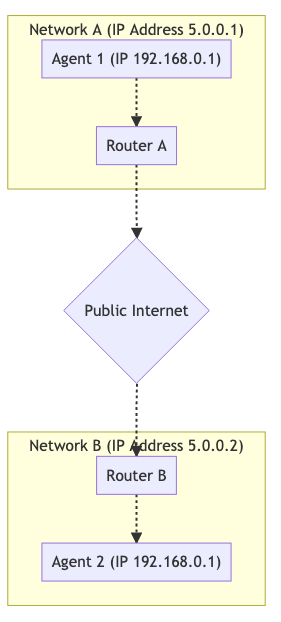
Different networks
In most cases, the second agent will be on a different network. Typically, a connection is established between agents located on different networks.
Below is a graph of two independent networks connected together via the public Internet. We have two hosts on each network.

For hosts on the same network, establishing a connection is a simple task. Communication between them 192.168.0.1 -> 192.168.0.2is easy to organize. Such hosts can communicate with each other without outside help.
However, a host using Router B. is not able to communicate with hosts using Router A. How to determine the difference between 192.168.0.1from Router Aand the same IPfrom Router B? These IPare private (closed to the outside world, private)! The host from Router Bcan send data to Router A, but the request will fail. How Router Ado you determine which host to send a message to?
Protocol Limitations
In some networks it is prohibited to transmit traffic via UDP, in others - via TCP. Some networks may have a very low Maximum Transmission Unit (MTU). There are a large number of network settings that can make communication difficult to say the least.
Firewall Rules
Another problem is "Deep Packet Inspection" and other filtering of network traffic. Some network administrators apply such software on a per-packet basis. In many cases, this software does not understand WebRTCand considers packets WebRTCto be suspicious packets UDPtransmitted over a port that is not included in the whitelist .
NAT Mapping
Displaying the result of Network Address Translation (NAT) (NAT Mapping) is the magic that makes connections WebRTCpossible. This is what allows two peers from different networks to communicate with each other. Let's look at how mapping works NAT.
NATdoes not use a relay, proxy or server. We have Agent 1and Agent 2, which are on different networks. Despite this, they can exchange data. This is what it looks like:
To enable such communication, we resort to mapping NAT. Agent 1uses the port 7000to establish a connection WebRTCwith Agent 2. 192.168.0.1:7000binds to 5.0.0.1:7000. This allows you Agent 2to "reach" Agent 1by sending packets to 5.0.0.1:7000. Creating a mapping NATis similar to the automatic version of port forwarding in a router.
The downside NATis that there is no single form of mapping (eg static port forwarding), and the behavior may vary across different networks. ISPs and hardware manufacturers may do this in different ways. In some cases, network administrators can disable it altogether.
The good news is that all of these features are monitored and taken into account, allowing the agent ICEto create the display NATand its attributes.
The document describing this process is RFC 4787.
Creating a NAT Mapping
Creating the display is the easy part. A mapping is created when we send a packet to an address outside our network. The mapping NATis simply temporary public ones IPand the port occupied by our NAT. Outgoing messages are rewritten in such a way that the created mapping becomes their source address. When you post a message to a display, it is automatically forwarded to the host inside the one that created it NAT. And this process gets complicated when it comes to the details of creating a display.
Options for creating a NAT mapping
Creating a display is divided into three categories.
Standalone (endpoint-independent) mapping
A separate display is created internally for each sender NAT. If we send two packets to two remote addresses, the same mapping is used for both packets. Both remote hosts will see the same IPsource port. When responses are received from hosts, they are passed to the same local listener.
This is the best case scenario. To make a call, at least one party must be of this type.
Address dependent mapping
A new mapping is created when a packet is sent to a new address. If we send two packets to two different hosts, two mappings are created. If we send two packets to the same remote host but on different ports, ONE mapping is created.
Address and port dependent display
A new mapping is created if the remote IPor port is different. If we send two packets to the same remote host but on different ports, two mappings are created.
NAT Mapping Filtering Options
Display filtering is the rules that determine who can use a display. There are three possible options:
Offline filtering
Anyone can use the display. We can share it with other peers and they can send traffic to it.
Address - dependent filtering
A mapping can only be used by the host that created it. If we send a packet to a host A, it can send back any number of packets. If the host Bsends a packet to this mapping, the packet will be ignored.
Address - and port-dependent filtering
The mapping can only be used by the host and port that created it. If we send a packet to a host A:5000, it can respond with any number of packets. The packet sent by host A:5001will be ignored.
Updating the NAT Mapping
It is recommended to destroy a display that is not used for five minutes, but this depends on ISPs and hardware manufacturers.
STUN
Session Traversal Utilities for NAT (STUN) is a protocol designed to work with NAT. It is defined in RFC 8489 , which also defines the packet structure STUN. The protocol STUNis also used ICE/TURN.
STUNallows you to programmatically create mappings NAT. Before, STUNwe could create mappings, but could not receive information about the created ones IPand the ports. STUNnot only allows you to create displays, it also provides information that can be shared with others so that they can feed data into the display.
Let's start with a basic description STUN. Later we will look at how STUNit is used in ICEand TURN. Let's look at the request/response process for creating a mapping, and also talk about how to get information about IPports. This process occurs when we have a server stun:in the paths (urls) ICEfor WebRTC PeerConnection(for example, new RTCPeerConnection({ iceServers: [{ urls: ['stun:stun.l.google.com:19302'] }] })). STUNhelps the endpoint behind NAT, to obtain details about the created mapping, by sending a request to the server STUNto provide information about what it sees from the outside (observes).
Protocol structure
Each package STUNhas the following structure:
0 1 2 3
0 1 2 3 4 5 6 7 8 9 0 1 2 3 4 5 6 7 8 9 0 1 2 3 4 5 6 7 8 9 0 1
+-+-+-+-+-+-+-+-+-+-+-+-+-+-+-+-+-+-+-+-+-+-+-+-+-+-+-+-+-+-+-+-+
|0 0| STUN Message Type | Message Length |
+-+-+-+-+-+-+-+-+-+-+-+-+-+-+-+-+-+-+-+-+-+-+-+-+-+-+-+-+-+-+-+-+
| Magic Cookie |
+-+-+-+-+-+-+-+-+-+-+-+-+-+-+-+-+-+-+-+-+-+-+-+-+-+-+-+-+-+-+-+-+
| |
| Transaction ID (96 bits) |
| |
+-+-+-+-+-+-+-+-+-+-+-+-+-+-+-+-+-+-+-+-+-+-+-+-+-+-+-+-+-+-+-+-+
| Data |
+-+-+-+-+-+-+-+-+-+-+-+-+-+-+-+-+-+-+-+-+-+-+-+-+-+-+-+-+-+-+-+-+
STUN Message Type
Package type. At the moment we are interested in the following:
- Binding Request - 0x0001;
- Binding Response - 0x0101.
To create the display NATwe execute Binding Request. The server sends us Binding Response.
Message Length
Section length Data(data size). This section contains data defined in Message Type.
Magic Cookie
Fixed value 0x2112A442in network byte order. This helps differentiate it STUNfrom other protocols.
Transaction ID
A 96-bit identifier that uniquely identifies the request/response. This helps identify request and response pairs.
Data
The data contains a list of attributes STUN. The attribute STUNhas the following structure:
0 1 2 3
0 1 2 3 4 5 6 7 8 9 0 1 2 3 4 5 6 7 8 9 0 1 2 3 4 5 6 7 8 9 0 1
+-+-+-+-+-+-+-+-+-+-+-+-+-+-+-+-+-+-+-+-+-+-+-+-+-+-+-+-+-+-+-+-+
| Type | Length |
+-+-+-+-+-+-+-+-+-+-+-+-+-+-+-+-+-+-+-+-+-+-+-+-+-+-+-+-+-+-+-+-+
| Value (variable) ....
+-+-+-+-+-+-+-+-+-+-+-+-+-+-+-+-+-+-+-+-+-+-+-+-+-+-+-+-+-+-+-+-+
STUN Binding Requestdoes not use attributes. This means that the request contains only a header.
STUN Binding Responseuses XOR-MAPPED-ADDRESS (0x0020). This attribute IPalso contains the port from the mapping NAT.
Creating a NAT Mapping
The “price” of creating a display NATusing STUNis one request. We send Binding Requestto the server STUN. He returns to us Binding Response. Binding Responsecontains Mapped Address. Mapped Address— how the server STUNsees the display NAT. Mapped Address- something that can be used by another party to send data to us.
Mapped Address- this is our Public IP(public address) or Server Reflexive Candidatein terminology WebRTC.
NAT Type Determination
Unfortunately, Mapped Addressit may not be used in all cases. If NATis address dependent, we can only receive data from the server STUN. In this case, messages sent by the other party to Mapped Addresswill be dropped. This makes it Mapped Addressuseless. And this problem is solved by the server STUNredirecting the packets to the peer. This solution is called TURN.
RFC 5780 describes a method for inferring a NAT. This allows you to determine in advance whether a direct connection can be established.
TURN
Traversal Using Relays around NAT (TURN), defined in RFC 8656, is a solution to the lack of direct connectivity. This can happen when types are incompatible NATor agents use different protocols. TURNcan also be used to ensure privacy. By creating communication using TURN, we obfuscate (hide) the real addresses of clients.
TURNuses a dedicated server. This server is a proxy for the client. The client connects to the server TURNand creates Allocation(location). It is allocated a temporary IP/port/protocol that can be used for data transmission. This handler is called Relayed Transport Address. This is a kind of forwarding address that can be used by another party to transmit traffic through TURN. For each peer, a separate one is created Relayed Transport Address, which requires granting Permission(permission) for communication.
When traffic is transmitted through TURN, it is transmitted through Relayed Transport Address. When a remote peer receives traffic, it sees that the traffic came from TURN.
Lifecycle of TURN
Let's talk about what a client who wants to create a placement in TURN. Communication with someone who uses TURNdoes not require additional actions. The other peer simply receives IPa port that can be used to transmit data.
Placements
Placements are the core TURN. Allocation- "session TURN". To create a location in TURNwe contact Server Transport Addressthe server TURN(the default port is 3478).
When creating a placement, the server must provide the following information:
- username/password - creating a placement requires authentication;
- transport used by the hosting - the transport protocol between the server ( Server Transport Address) and peers: UDPor TCP;
- Even-Port- we can request a sequence of ports for multiple non- WebRTC.
If the request is successful, we receive TURNa response from the server with the following attributes in the section Data:
- XOR-MAPPED-ADDRESS— Mapped Addressclient TURN(TURN Client). When sending data to Relayed Transport Address, it is redirected to this address;
- RELAYED-ADDRESS— address transmitted to other clients. When a packet is sent to this address, it is transmitted to the client TURN;
- LIFETIME— how much time is left before the placement is destroyed TURN. The lifetime of an allocation can be increased by sending a request Refresh.
Permissions
The remote host cannot send data to ours Relayed Transport Addressuntil we grant it permission. When creating a permission, we tell the server TURNthat IPincoming traffic is allowed on the specified port.
The remote host must provide us IPwith the port as they appear on the server TURN. This means he must send STUN Binding Request. A common mistake is sending such a request to the wrong server TURN. After sending the request, the remote host contacts us asking for permission.
Let's say we want to create a permission for a host located behind Address Dependent Mapping. If we receive Mapped Addressfrom another server TURN, all incoming traffic will be lost. Each time you interact with another host, a new mapping is created. The lifetime of the permit is 5 minutes.
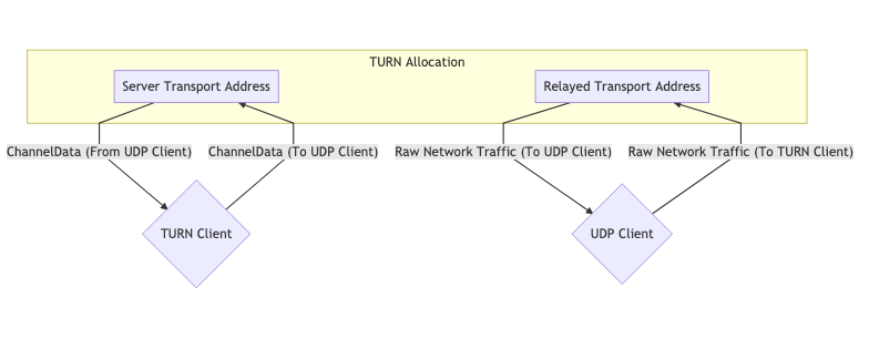
SendIndication/ChannelData
These messages are for the client TURNto send messages to the remote peer.
SendIndication - a self-contained message. Inside it is the data to be sent, as well as the recipient. Sending a large number of messages to a remote peer is wasteful. When sending 1000 messages, IPthe remote peer's address will be repeated 1000 times!
ChannelDataallows you to send data without duplication IP-адреса. We create a channel with IPand port. When a message is sent, it indicates ChannelId, and IPthe port is filled in by the server. This allows you to reduce the load on the server when sending a large number of messages.
Update
Placements are destroyed automatically. To maintain placement, its LIFETIME(lifetime) must be updated periodically.
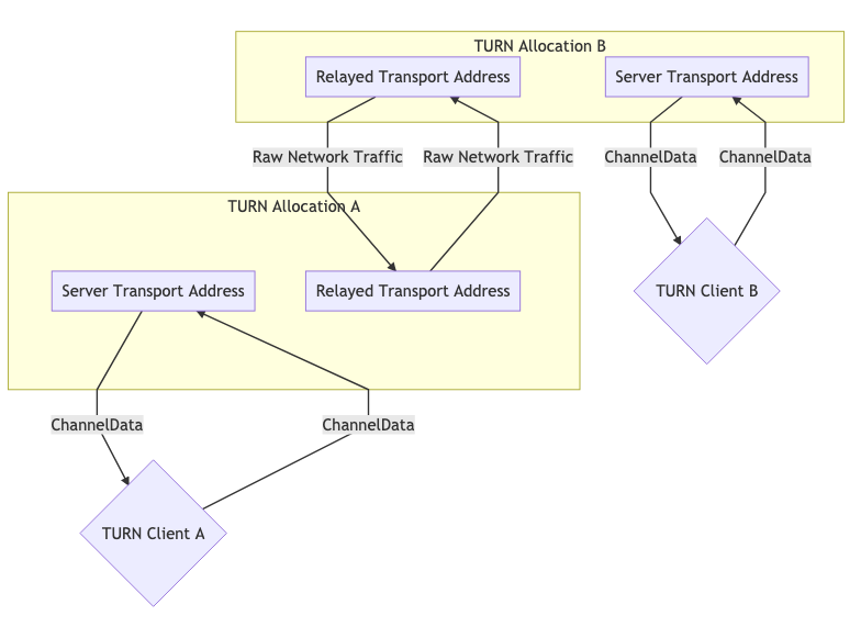
Using TURN
TURNcan be used in two forms. Typically, we have one peer acting as the "client TURN" and another peer accessing the "client" directly. In some cases it may be necessary to use TURNon both sides, for example because both sides are on networks that block UDP, so the connection to the respective servers TURNis made through TCP.
One TURN allocation for communication
Two TURN allocations for communication
ICE
ICE— how WebRTCit connects two agents. This protocol is defined in RFC 8445. ICE— protocol for establishing a connection. It describes all possible routes between two peers and ensures connection stability.
These routes are called Candidate Pairs(candidate pairs) and represent a pair of local and remote transport addresses. This is where STUNand come into play TURN. These addresses can be our local IPand port, mapping NATor Relayed Transport Address. Each side collects the addresses it wants (and can) use, passes them on to the other side, and attempts to connect.
Two agents ICEcommunicate using ping packets ICE(formally called connectivity checks) to establish a connection. Once the connection is established, the parties can exchange data. This is similar to using regular websockets. All necessary checks are performed using the protocol STUN.
Creating an ICE Agent
An agent ICEcan be Controlling(manager) or Controlled(managed). The managing agent is the one who selects Candidate Pair. Typically, the peer sending the offer is the control party.
Each side must have user fragmentand password. The parties must exchange these values before starting connectivity checks. user fragmentsent in plain text and can be used to demuxing multiple sessions ICE. passwordused to generate the attribute MESSAGE-INTEGRITY. At the end of each packet STUNthere is an attribute with a hash of the contents of the packet - passwordused as a key. This allows the packet to be authenticated, i.e. make sure that it has not been replaced or modified during the transfer process.
In the case of, WebRTCthese values are passed through Session Description(session description), which was discussed in the previous section.
Candidate Gathering
Now we need to collect all the addresses at which agents are reachable. These addresses are called candidates.
Host
The host candidate is provided by the local interface. It could be UDPor TCP.
mDNS
The candidate mDNSis similar to the host candidate, but is IP-адресhidden. Instead, IP-адресаthe other party is provided UUID as the host name. After that, we set up a multicast listener that responds to requests to the published UUID.
If we are on the same network as the agent, we can find each other via multicast. If we and the agent are on different networks, the connection will not be established. At a minimum, until the network administrator explicitly allows such packet transfer.
This allows for confidentiality. In the case of the host candidate, the user sees our IPaddress through WebRTC(without even trying to establish a connection), but in the case of the candidate, mDNShe will only receive a random one UUID.
Server Reflexive
The Server Reflexive Candidate is generated by the server STUNin response to STUN Binding Request.
When received, STUN Binding Responsethe content contained in it XOR-MAPPED-ADDRESSis our candidate from the server.
Peer Reflexive
Peer Reflexive Candidate is when we receive an incoming request from an unknown address. Since ICEit is an authenticated protocol, we know that the traffic is valid. This just means that the remote peer is communicating with us from an unknown address.
This usually happens when communicating Host Candidatewith Server Reflexive Candidate. Since we are communicating outside of our subnet, a new mapping is created NAT. Remember when we said that connection checks are actually packets STUN? The response format STUNallows the peer to return the peer's candidate address (peer-reflexive address).
Relay
The relay candidate is generated by the server TURN.
After the initial handshake, we receive RELAYED-ADDRESSour relay candidate.
Connection checks
Now we know the remote agent candidates user fragment. passwordWe are trying to connect! Candidates are divided into pairs. So if we had three candidates from each side, we end up with nine pairs of candidates.
This is what it looks like:
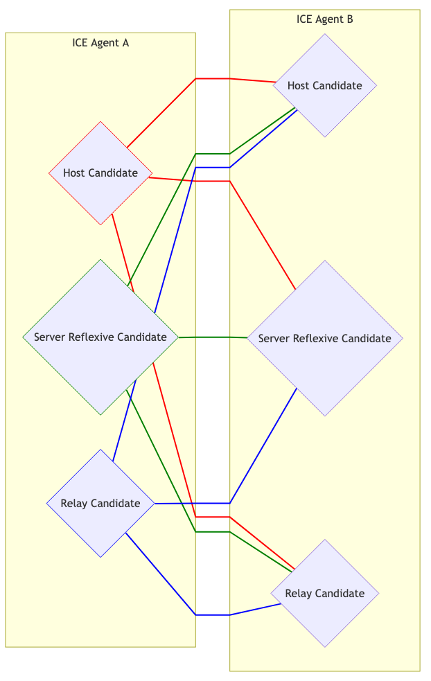
Selection of candidates
The managing and managed agents begin transmitting traffic through each pair. This is required when one agent is behind Address Dependent Mapping, resulting in the creation of Peer Reflexive Candidate.
Each Candidate Pair(pair of candidates) that “sees” the traffic becomes a pair of Valid Candidate(valid candidates). The managing agent takes one Valid Candidateand nominates him. The candidates nominated by the parties become Nominated Pairthe (nominated pair). The agents again attempt to establish bidirectional communication. If successful, Nominated Pairbecomes Selected Candidate Pair(the selected or chosen pair of candidates). This pair is used for the remainder of the session.
Reboot
If Selected Candidate Pairit stops working for any reason (the lifetime of the display has expired NAT, the server has crashed TURN), the agent ICEgoes into the state Failed. Both agents can be restarted and the process will start over.
This completes the first part of the translation.
Thank you for your attention and happy coding!
(c) https://webrtcforthecurious.com
Last edited:


