Hacker
Professional
- Messages
- 1,041
- Reaction score
- 853
- Points
- 113
The content of the article
Modern iron
First of all, it was decided to choose more relevant hardware as the target. The Arduino and the AVR are wonderful, our legacy, and must be treated with proper respect, not broken right and left. But today microcontrollers on the ARM core (Cortex-M) rule the ball. And most likely, you will find them, having gutted the nearest smart device - a wireless outlet, a light bulb with Wi-Fi and other delights of dubious automation.
At first glance, the budget STM32F091 (Cortex-M0) microcontroller on the Nucleo-64 board was ideal for the role of a guinea pig. Compared to the Arduino Nano, this solution looks advantageous literally in all respects: 32-bit capacity (versus eight), a clock frequency of 48 MHz (versus sixteen) and a supply voltage of only 3.3 V versus five. As for the price, you need to consider that the original Italian Arduino boards cost at least the same, if not more expensive.
This choice actually complicates the attack - not every budget oscilloscope will be able to keep up with the microcontroller at such speeds. Using Hantek DSO6022 from the presentation would have been doomed to failure in advance, just look at its characteristics.
Fortunately, I had a Rohde & Schwarz RTC1002 oscilloscope on my desk. According to the promotional materials, this is an entry-level model, but it's a deceiving impression. Yes, such an oscilloscope costs like a flagship smartphone, but it has a lot of useful functions and it is as convenient as possible.
The essence of the attack
I decided not to change the rest of the conditions of the initial competition. We will continue to analyze the power consumption traces of our device at the time of data encryption and try to guess the password stored in memory. Cipher - AES in ECB mode with a key length of 128 bits.
Of course, in practice, in a real device, you will most likely find AES in CBC mode, but I still have not figured out how to organically fit the initialization vector into the problem conditions. By itself, an IV without an encryption key is of little value to an attacker and is often transmitted in cleartext (an example of this is the SSL / TLS protocols, see RFC 5246).
The AES algorithm itself is considered one of the best, it is used almost everywhere, and to date, no real vulnerabilities are known for it. What can go wrong and do we even have a chance of success?
The point is that the operations of any processor at the lowest level are reduced to switching transistors. This consumes energy, the consumption of which can be recorded. Knowing the encryption algorithm, input data and measuring the power parameters, we can try to guess the binary representation of the key (the number of transistors in the active state). And this will definitely be much better than a simple search! (Anything is better than brute force, to be honest.)
Of course, in practice, everything will not be so easy: in any modern circuit there are indecently many transistors, there are nonlinear processes, external interference is almost always inevitable, and the very attempt to take measurements inevitably makes a negative contribution to the accuracy of the data obtained.
Fortunately, we will have statistics on our side - if we can collect enough information, the useful signal will prevail over the noise and we will be able to find out the key. In our case, we are talking about five thousand oscillograms, each with thirty thousand points. I would call it "big data", but experts will probably laugh, so we will do without loud statements.
Thus, the principle of the attack is as follows: we send a random set of numbers from the computer to the input of the device under investigation, the device encrypts them and sends them back, and the oscilloscope closely monitors the power consumption (the utility meters never dreamed of such accuracy). After that, on command from the computer, we save the waveform and data set (input and output) and repeat the process.
In theory, everything looks seductively simple, doesn't it? How many times have I been so wrong.
Preparing the board
Let's start with the debug board: you have to spoil it a little, but there's nothing you can do about it. First of all, we will remove from the PCB all unnecessary things that can somehow consume or accumulate energy - we need the cleanest signal from the microcontroller itself, and not from the capacitors from its strapping.
We break off the ST-Link programmer - wide slots in the board itself hint that it will work perfectly well separately from the main part. If you are afraid to damage the board and rip out a whole piece, first try to file the connections with a regular hacksaw, it should be easier right away.
Now it's the turn of the capacitors in the power circuit. The microcontroller requires 3.3V, but it is an Arduino compatible board, and it is designed for an external 5V power supply, the LD39050PU33R linear DC / DC converter is responsible for this. The fact that it is linear is good, there would be unnecessary interference from the impulse.
Capacitors C20 and C21 at the input can be left, but C18 and C19 are clearly superfluous, feel free to take the soldering iron in your hands and solder it. Yes, they were not here! Capacitors C23, C24, C27 and C28 are also completely optional. They have some funny capacities - 100 nF - you can even ignore them. Liked? Everyone, stop, let the rest live!
Now about the sad things. We broke off the programmer before, but we still need it. You didn't throw it away, did you? It was very thoughtful! And it's not that we need the programmer in order to flash the microcontroller. No, this, it turns out, is also an adapter from USB to UART, and with its help we will communicate with the computer.
The problem is that the RX / TX tracks of the UART interface were located exactly on the jumpers that we cut before. On the programmer, these signals are available on the CN3 connector, but on the board with F091 itself, the D0 / D1 pins of the CN9 connector are not connected to the microcontroller. Jumpers SB62 and SB63 on the back of the board are responsible for this, so connect them with a couple of drops of solder.
By the way, did you notice that there is no quartz resonator on the board in place of X3? There is a 32.768 kHz clock crystal in place of X2, but this is for the RTC. It turns out that ST-Link, in addition to performing its main functions, also generates a reference frequency of 8 MHz for the main microcontroller! This is the MCO line on the diagram (pin PF0).
Unlike the UART interface, this signal is not output to any pins, and without it, F091 will definitely refuse to work. I could not think of anything better than buying an 8 MHz crystal oscillator at the nearest radio parts store . It should be connected to the 5 V line. In this case, the square wave will be with an amplitude of 5 V instead of the prescribed 3.3 V, but this is not scary, since the PF0 pin is designated in the datasheet on the microcontroller as FT, that is, compatible with five-volt logic.
It remains only to unsolder the SB50 jumper and solder the SB55 to bring the PF0 leg to the 29th pin of the CN7 connector. It is likely that now you are only interested in one thought: why did the developers at ST come up with such a complex scheme? It turns out that the entire Nucleo-64 debug lineup is based on such a printed circuit board , and these are almost twenty different versions. The specific version features a combination of all these tiny jumpers.
We write the firmware
Now we need a software implementation of the AES algorithm. After the RHme2 competition, Riscure employees posted the source code of the examples on their GitHub. But you won't be able to use them for the simple reason that they are platform dependent. AES cipher substitution tables are pgm_read_byteprogrammed using macros in a flash, which is expanded into a chain of assembler instructions for the AVR.
It is clear that for F091 on ARM, such a code cannot be run. Therefore, I chose a third-party AES implementation in ECB mode, adding the missing pieces myself. In general, this was the simplest part, the program logic completely repeats the principle of operation of the original example from RHme2. A pre-generated randomly generated AES key will be stored in the device itself:
Why an oscilloscope needs Ethernet
Having tested the functionality of the board and firmware in the "Port Monitor" from the Arduino IDE, I manually caught a couple of oscillograms at the time of encrypting messages. The first tracks looked something like this.
Guessing ten AES rounds here is possible only with a very strong desire. The ratio of noise and useful signal on the oscillogram left much to be desired. By increasing the sample rate and playing around with the filter settings on the device, I was able to get more decent frames.
The same jumps in power consumption are clearly visible when moving from one round to another - this pattern is difficult to confuse with something, and you can guess the key length here purely visually (by the number of signal repetitions).
Now it was necessary to somehow automate the collection and saving of oscillograms. Rohde & Schwarz suggests using the HMExplorer utility on their website , but after a quick look at the documentation, I came to the disappointing conclusion that its capabilities were not enough for me.
It's one thing to simply remotely control the instrument from a computer via GPIB or Ethernet using the SCPI instruction set. But I still had to simultaneously take the entropy from /dev/urandomand send it to the microcontroller via the serial port. It was easier to write the implementation yourself.
Above, I mentioned the SCPI suite - this is a standardized way of interacting with tools from a variety of manufacturers. I found a quick reference on the commands at the end of the documentation for the RTC1002 oscilloscope itself, but in addition R&S has a comprehensive SCPI Programming Manual .
In fact, across the large set, we have three kinds of instructions. Common commands support all standard-compatible devices. They allow us to find out which specific device we are working with now.
Next come the basic commands, which determine the state and operation of the tool. They have a long form (all characters in the message) and a short form (only uppercase characters).
Finally, we have commands for specific instrument settings. They make up the bulk of the SCPI suite and are nested within various namespaces for convenience. You can set the sampling rate, vertical and horizontal deviation, trigger delay and much more. In general, literally any menu item is remotely accessible here. Moreover, you can send your own messages over the network and display them on the screen.
Thus, by connecting the oscilloscope to the same network with a laptop and setting the IP addresses, you can work with the device via sockets from any C program:
Putting it all together
To complete the preparatory stage, it remains to implement exactly two things: working with the serial port and receiving random numbers from the entropy source in the system. In general, nothing complicated, but there are a couple of nuances:
As for the random numbers, in fact they could be generated directly on the microcontroller. And even a separate hardware TRNG is completely optional here. If the task is to get entropy from the "cheap and cheerful" category, you can get by with noise in the ADC, I recently wrote an article about this in "Hacker".
Now all that remains is to collect all this into a single file main.c, and you can start the process. It's a good time to drink some tea and think about what to do next.
Preprocessing
After a while, I already had five thousand oscillograms in CSV format and a binary file from the debug board on my laptop. However, before analyzing the traces in the Jlsca statistical package, the data had to be converted to TRS format.
Generally speaking, one had to make sure beforehand that the common patterns on the oscillogram (peaks and troughs) correspond to the rounds of the AES algorithm and the traces themselves are synchronized. In other words, we need to be sure that we are comparing the internal state of the microcontroller at the same time, otherwise all other work loses all meaning.
Such desynchronization may well occur due to phase jitter of the signal (jitter) on the channel with the trigger, and it all depends on the characteristics of your oscilloscope, how quickly it can react and start capturing data on the main channel.
Fortunately, I could visually observe the oscillograms on the instrument screen while collecting power traces, and after some time I came to the conclusion that this step could be skipped. However, in the original presentation, the Riscure instructor still had to level the tracks, mainly due to the budget of the Hantek model.
Let's go back to the oscillograms. Of course, the exponential representation of numbers in the columns of CSV files could also be parsed and converted using the C language.However, I could not find a description of the TRS format from Riscure, but I did find a module for Python.
Let's write a couple of scripts:
Now let's merge all the files together:
The module numpyalready contains a ready-made method for reading sequences from text files, so all the code is simple to disgrace. The output should be an impressive file with all traces and pairs "plain text - ciphertext".
By the way, if you repeat all this in macOS, please note that the module is trsfileused mmapto work with files .trs, and the Apple operating system does not support resizing a file already in memory. So the script will keep throwing an error. The easiest option is to go to Linux and build the file there, which I did using Ubuntu in a virtual machine.
Who is Julia
The data obtained will be analyzed using the Jlsca package. This is another open source development from Riscure (you can download it for free on GitHub). The utility is written in the young language Julia, which in theory promises good performance in complex calculations and scientific calculations.
Arguments at startup are passed to the program in a somewhat unusual way - through the file name. You need to specify the algorithm, encryption mode and (optionally) the correct key. In my case, the name is derived as follows: aes128_sb_ciph_47f1ed9166c996b2f553b147be3fbc20.
In addition, since we are calculating the Hamming weight for our data, we need to add the appropriate line to the file main-condavg.jl.
Do you cross your fingers for luck? Here's another nonsense.
To be honest, I didn't manage to get the correct result right away. I ruined my first attempt by not carefully reading the circuit diagram of the board and not removing all the necessary capacitors in the power circuit. Moreover, I forgot to add "plaintext - ciphertext" sets to the traces. As a result, the program was not even close to guessing a single correct byte in the key.
The second approach turned out to be more successful, but, apparently, the sample size was not enough for me. I collected a thousand waveforms from the device at the time of encryption, and the results were much better - the coefficients for the required bytes hit the top 10, and this was encouraging. However, the ratio of noise to wanted signal was still far from ideal.
Only the third attempt was successful, but, probably, this is also a good result! I had to increase the data array five times, and also revise the power scheme by adding an external 3.3 V voltage regulator. I don’t know if this played a role or not, but as a source of electricity I chose not an external battery with Li-Pol and a pulse DC / DC converter, and a regular 9V battery.
Summing up
If you try to describe my impressions of the work done in one word, then perhaps the best word would be “mixed”. On the one hand, it was incredibly interesting, along the way I had to solve several non-trivial problems, figure out things new to myself, and in general I do not regret the time spent.
Moreover, it is worth recognizing that such attacks really should be considered among the threats to the security of the device and the privacy of user data. Of course, extracting the encryption key from a modern microcontroller on the ARM core was not as easy as in the case of its AVR ancestor, and the equipment for the attack had to be more expensive. But, as you can see, there were not many fundamental differences.
On the other hand, a researcher from Riscure stated in his speech that today attacks through secondary channels can already be carried out almost by script kiddies. I don't know, maybe he was referring to the original RHme2 competition, or they have some other script kiddies in Europe, the level is significantly higher than ours. In any case, personally, it took me a lot of time to prepare for the attack and transfer the example to the actual hardware.
Additional materials
Having examined in detail the existing threat, one cannot but say a few words about how to protect against it. I’m unlikely to come up with something new here, but I can recommend several good sources where you will definitely find useful information. This is primarily a collection of Riscure recommendations for developers and security professionals Secure Application Programming . In addition, the material " Attacks on Embedded Systems" by BI.Zone deserves to be studied. AVK on energy consumption and AMIS on nutrition are discussed in sufficient detail there.
P.S
For me personally, the issue with such threats is not yet closed. First, I would like to find a suitable device and conduct an experiment under conditions as close as possible to reality. Secondly, who needs a software implementation of encryption, if today hardware accelerators of cryptographic computations appear in embedded systems in general and microcontrollers in particular?
Whether they are vulnerable to such attacks and how realistic it is with low-end equipment - this point deserves the most careful study. Anyway, I intend to return to AVK in a while and may appear with new material. Unless, of course, you get ahead of me.
- Modern iron
- The essence of the attack
- Preparing the board
- We write the firmware
- Why an oscilloscope needs Ethernet
- Putting it all together
- Preprocessing
- Who is Julia
- Summing up
- Additional materials
- P.S
Modern iron
First of all, it was decided to choose more relevant hardware as the target. The Arduino and the AVR are wonderful, our legacy, and must be treated with proper respect, not broken right and left. But today microcontrollers on the ARM core (Cortex-M) rule the ball. And most likely, you will find them, having gutted the nearest smart device - a wireless outlet, a light bulb with Wi-Fi and other delights of dubious automation.
At first glance, the budget STM32F091 (Cortex-M0) microcontroller on the Nucleo-64 board was ideal for the role of a guinea pig. Compared to the Arduino Nano, this solution looks advantageous literally in all respects: 32-bit capacity (versus eight), a clock frequency of 48 MHz (versus sixteen) and a supply voltage of only 3.3 V versus five. As for the price, you need to consider that the original Italian Arduino boards cost at least the same, if not more expensive.
This choice actually complicates the attack - not every budget oscilloscope will be able to keep up with the microcontroller at such speeds. Using Hantek DSO6022 from the presentation would have been doomed to failure in advance, just look at its characteristics.
Fortunately, I had a Rohde & Schwarz RTC1002 oscilloscope on my desk. According to the promotional materials, this is an entry-level model, but it's a deceiving impression. Yes, such an oscilloscope costs like a flagship smartphone, but it has a lot of useful functions and it is as convenient as possible.
The essence of the attack
I decided not to change the rest of the conditions of the initial competition. We will continue to analyze the power consumption traces of our device at the time of data encryption and try to guess the password stored in memory. Cipher - AES in ECB mode with a key length of 128 bits.
Of course, in practice, in a real device, you will most likely find AES in CBC mode, but I still have not figured out how to organically fit the initialization vector into the problem conditions. By itself, an IV without an encryption key is of little value to an attacker and is often transmitted in cleartext (an example of this is the SSL / TLS protocols, see RFC 5246).
The AES algorithm itself is considered one of the best, it is used almost everywhere, and to date, no real vulnerabilities are known for it. What can go wrong and do we even have a chance of success?
The point is that the operations of any processor at the lowest level are reduced to switching transistors. This consumes energy, the consumption of which can be recorded. Knowing the encryption algorithm, input data and measuring the power parameters, we can try to guess the binary representation of the key (the number of transistors in the active state). And this will definitely be much better than a simple search! (Anything is better than brute force, to be honest.)
Of course, in practice, everything will not be so easy: in any modern circuit there are indecently many transistors, there are nonlinear processes, external interference is almost always inevitable, and the very attempt to take measurements inevitably makes a negative contribution to the accuracy of the data obtained.
Fortunately, we will have statistics on our side - if we can collect enough information, the useful signal will prevail over the noise and we will be able to find out the key. In our case, we are talking about five thousand oscillograms, each with thirty thousand points. I would call it "big data", but experts will probably laugh, so we will do without loud statements.
Thus, the principle of the attack is as follows: we send a random set of numbers from the computer to the input of the device under investigation, the device encrypts them and sends them back, and the oscilloscope closely monitors the power consumption (the utility meters never dreamed of such accuracy). After that, on command from the computer, we save the waveform and data set (input and output) and repeat the process.
In theory, everything looks seductively simple, doesn't it? How many times have I been so wrong.
Preparing the board
Let's start with the debug board: you have to spoil it a little, but there's nothing you can do about it. First of all, we will remove from the PCB all unnecessary things that can somehow consume or accumulate energy - we need the cleanest signal from the microcontroller itself, and not from the capacitors from its strapping.
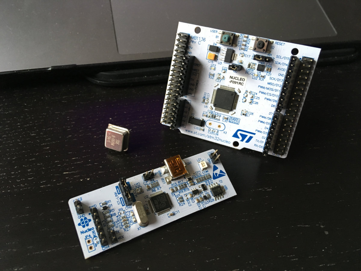
We break off the ST-Link programmer - wide slots in the board itself hint that it will work perfectly well separately from the main part. If you are afraid to damage the board and rip out a whole piece, first try to file the connections with a regular hacksaw, it should be easier right away.
Now it's the turn of the capacitors in the power circuit. The microcontroller requires 3.3V, but it is an Arduino compatible board, and it is designed for an external 5V power supply, the LD39050PU33R linear DC / DC converter is responsible for this. The fact that it is linear is good, there would be unnecessary interference from the impulse.
Capacitors C20 and C21 at the input can be left, but C18 and C19 are clearly superfluous, feel free to take the soldering iron in your hands and solder it. Yes, they were not here! Capacitors C23, C24, C27 and C28 are also completely optional. They have some funny capacities - 100 nF - you can even ignore them. Liked? Everyone, stop, let the rest live!
Now about the sad things. We broke off the programmer before, but we still need it. You didn't throw it away, did you? It was very thoughtful! And it's not that we need the programmer in order to flash the microcontroller. No, this, it turns out, is also an adapter from USB to UART, and with its help we will communicate with the computer.
The problem is that the RX / TX tracks of the UART interface were located exactly on the jumpers that we cut before. On the programmer, these signals are available on the CN3 connector, but on the board with F091 itself, the D0 / D1 pins of the CN9 connector are not connected to the microcontroller. Jumpers SB62 and SB63 on the back of the board are responsible for this, so connect them with a couple of drops of solder.
By the way, did you notice that there is no quartz resonator on the board in place of X3? There is a 32.768 kHz clock crystal in place of X2, but this is for the RTC. It turns out that ST-Link, in addition to performing its main functions, also generates a reference frequency of 8 MHz for the main microcontroller! This is the MCO line on the diagram (pin PF0).
Unlike the UART interface, this signal is not output to any pins, and without it, F091 will definitely refuse to work. I could not think of anything better than buying an 8 MHz crystal oscillator at the nearest radio parts store . It should be connected to the 5 V line. In this case, the square wave will be with an amplitude of 5 V instead of the prescribed 3.3 V, but this is not scary, since the PF0 pin is designated in the datasheet on the microcontroller as FT, that is, compatible with five-volt logic.
It remains only to unsolder the SB50 jumper and solder the SB55 to bring the PF0 leg to the 29th pin of the CN7 connector. It is likely that now you are only interested in one thought: why did the developers at ST come up with such a complex scheme? It turns out that the entire Nucleo-64 debug lineup is based on such a printed circuit board , and these are almost twenty different versions. The specific version features a combination of all these tiny jumpers.
We write the firmware
Now we need a software implementation of the AES algorithm. After the RHme2 competition, Riscure employees posted the source code of the examples on their GitHub. But you won't be able to use them for the simple reason that they are platform dependent. AES cipher substitution tables are pgm_read_byteprogrammed using macros in a flash, which is expanded into a chain of assembler instructions for the AVR.
It is clear that for F091 on ARM, such a code cannot be run. Therefore, I chose a third-party AES implementation in ECB mode, adding the missing pieces myself. In general, this was the simplest part, the program logic completely repeats the principle of operation of the original example from RHme2. A pre-generated randomly generated AES key will be stored in the device itself:
Code:
/ * Key is: 0x47f1ed9166c996b2f553b147be3fbc20 (128-bit) * /
const uint8_t key [] = {0x47, 0xF1, 0xED, 0x91, 0x66, 0xC9, 0x96,
    0xB2, 0xF5, 0x53, 0xB1, 0x47, 0xBE, 0x3F, 0xBC, 0x20};
Why an oscilloscope needs Ethernet
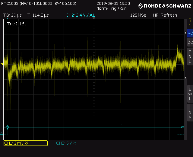
Having tested the functionality of the board and firmware in the "Port Monitor" from the Arduino IDE, I manually caught a couple of oscillograms at the time of encrypting messages. The first tracks looked something like this.
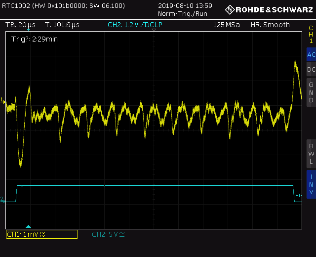
Guessing ten AES rounds here is possible only with a very strong desire. The ratio of noise and useful signal on the oscillogram left much to be desired. By increasing the sample rate and playing around with the filter settings on the device, I was able to get more decent frames.
The same jumps in power consumption are clearly visible when moving from one round to another - this pattern is difficult to confuse with something, and you can guess the key length here purely visually (by the number of signal repetitions).
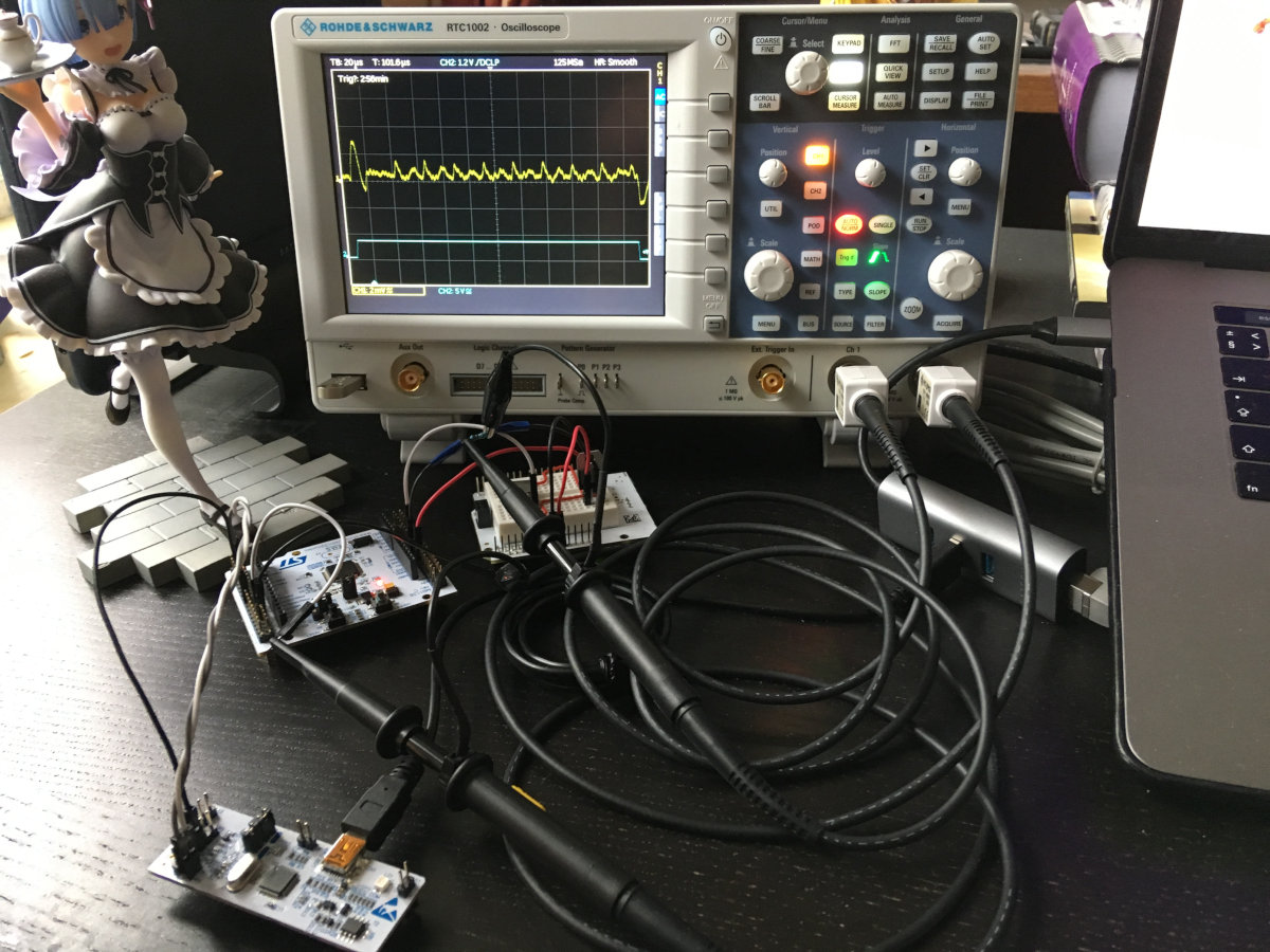
Now it was necessary to somehow automate the collection and saving of oscillograms. Rohde & Schwarz suggests using the HMExplorer utility on their website , but after a quick look at the documentation, I came to the disappointing conclusion that its capabilities were not enough for me.
It's one thing to simply remotely control the instrument from a computer via GPIB or Ethernet using the SCPI instruction set. But I still had to simultaneously take the entropy from /dev/urandomand send it to the microcontroller via the serial port. It was easier to write the implementation yourself.
Above, I mentioned the SCPI suite - this is a standardized way of interacting with tools from a variety of manufacturers. I found a quick reference on the commands at the end of the documentation for the RTC1002 oscilloscope itself, but in addition R&S has a comprehensive SCPI Programming Manual .
In fact, across the large set, we have three kinds of instructions. Common commands support all standard-compatible devices. They allow us to find out which specific device we are working with now.
Code:
/ * CMD: * IDN?
 * ANS: ROHDE & SCHWARZ, RTC1002, XXXXXXXXX, YYY.ZZZ
 * /
Next come the basic commands, which determine the state and operation of the tool. They have a long form (all characters in the message) and a short form (only uppercase characters).
Code:
/ * CMD: RUNContinous (RUNC)
 * ANS: None
 * /
Finally, we have commands for specific instrument settings. They make up the bulk of the SCPI suite and are nested within various namespaces for convenience. You can set the sampling rate, vertical and horizontal deviation, trigger delay and much more. In general, literally any menu item is remotely accessible here. Moreover, you can send your own messages over the network and display them on the screen.
Code:
/ * CMD: DISPlay: DIALog :: MESSage (DISP: DIAL: MESS)
 * ANS: None
 *
 * CMD: CHANnel1: DATA: HEADer? (CHAN1: DATA: HEAD?)
 * ANS: -9.477E-008.9.477E-008.30000.1
 * /
Thus, by connecting the oscilloscope to the same network with a laptop and setting the IP addresses, you can work with the device via sockets from any C program:
Code:
#include <stdio.h>
#include <stdlib.h>
#include <string.h>

#include <sys / socket.h>
#include <arpa / inet.h>
#include <unistd.h>

#define PORT (5025)
#define HOST ("192.168.10.11")
#define SCPI_BUFFER (512)

int scpi_init (char * ip, int port) {
  int sd = socket (AF_INET, SOCK_STREAM, 0);
  struct sockaddr_in server = {.sin_family = AF_INET,
                               .sin_port = htons (port)};

  inet_pton (AF_INET, ip, & server.sin_addr);
  connect (sd, (struct sockaddr *) & server, sizeof (server));

  return sd;
}

int scpi_cmd_write (int sd, char * cmd) {
  return write (sd, cmd, strlen (cmd));
}

int scpi_cmd_read (int sd, char * cmd, char * b) {
  if (scpi_cmd_write (sd, cmd)! = strlen (cmd)) {
    return -1;
  }

  return read (sd, b, SCPI_BUFFER);
}
Putting it all together
To complete the preparatory stage, it remains to implement exactly two things: working with the serial port and receiving random numbers from the entropy source in the system. In general, nothing complicated, but there are a couple of nuances:
Code:
int uart_open (char * path) {
  int fd = open (path, O_RDWR | O_ASYNC);
  struct termios attr;

  / * Set parameters for UART communication * /
  tcgetattr (fd, & attr);
  cfsetospeed (& attr, B115200);
  cfsetispeed (& attr, B115200);
  attr.c_cflag & = ~ (PARENB | CSTOPB | CSIZE);
  attr.c_cflag | = CS8 | CLOCAL;
  attr.c_lflag = ICANON;
  attr.c_oflag & = ~ OPOST;

  tcsetattr (fd, TCSANOW, & attr);
  tcflush (fd, TCIOFLUSH);

  return fd;
}

int uart_recv (int fd, char * b, int len) {
  int i = 0;

  for (char c = 0; i <len && c! = '\ n'; ++ i) {
    read (fd, & c, 1);
    b [i] = c;
  }

  return i;
 }

int uart_send (int fd, char * b, int len) {
  return write (fd, b, len) ;;
}

int uart_close (int fd) {
  return close (fd);
}
As for the random numbers, in fact they could be generated directly on the microcontroller. And even a separate hardware TRNG is completely optional here. If the task is to get entropy from the "cheap and cheerful" category, you can get by with noise in the ADC, I recently wrote an article about this in "Hacker".
Code:
char vLUT (char n) {
  return n> = 10? n + 'A' - 10: n + '0';
}

void get_rand (char * buffer, int n) {
  int rd = open ("/ dev / urandom", O_RDONLY);

  read (rd, buffer, n);
  close (rd);

  for (int i = 0; i <n; ++ i) {
    buffer [i] & = 0x0F;
    buffer [i] = vLUT (buffer [i]);
  }
}
Now all that remains is to collect all this into a single file main.c, and you can start the process. It's a good time to drink some tea and think about what to do next.
Preprocessing
After a while, I already had five thousand oscillograms in CSV format and a binary file from the debug board on my laptop. However, before analyzing the traces in the Jlsca statistical package, the data had to be converted to TRS format.
Generally speaking, one had to make sure beforehand that the common patterns on the oscillogram (peaks and troughs) correspond to the rounds of the AES algorithm and the traces themselves are synchronized. In other words, we need to be sure that we are comparing the internal state of the microcontroller at the same time, otherwise all other work loses all meaning.
Such desynchronization may well occur due to phase jitter of the signal (jitter) on the channel with the trigger, and it all depends on the characteristics of your oscilloscope, how quickly it can react and start capturing data on the main channel.
Fortunately, I could visually observe the oscillograms on the instrument screen while collecting power traces, and after some time I came to the conclusion that this step could be skipped. However, in the original presentation, the Riscure instructor still had to level the tracks, mainly due to the budget of the Hantek model.
Let's go back to the oscillograms. Of course, the exponential representation of numbers in the columns of CSV files could also be parsed and converted using the C language.However, I could not find a description of the TRS format from Riscure, but I did find a module for Python.
Let's write a couple of scripts:
Code:
# Remove all timestamps from files
TOTAL = 5000

for i in range (TOTAL):
  source = open ('TRC / TRC {: 04} .csv'.format (i),' r ')
  target = open ('traces / traces {: 04} .txt'.format (i),' w ')

  source.readline () # skip header
  for line in source.readlines ():
    time, volt = line.split (',')
    target.write (volt)

  source.close ()
  target.close ()
Now let's merge all the files together:
Code:
# Create resulting .trs file
import numpy as npy
import trsfile as trs

TOTAL = 5000

target = trs.trs_open ('result.trs', 'w', padding_mode = trs.TracePadding.AUTO)

bytes = open ('data.bin', 'rb')

for i in range (TOTAL):
  source = npy.genfromtxt ('traces / traces {: 04} .txt'.format (i), dtype = float)
  target.append (trs.Trace (trs.SampleCoding.FLOAT, source, data = bytes.read (32)))

bytes.close ()
target.close ()
The module numpyalready contains a ready-made method for reading sequences from text files, so all the code is simple to disgrace. The output should be an impressive file with all traces and pairs "plain text - ciphertext".
By the way, if you repeat all this in macOS, please note that the module is trsfileused mmapto work with files .trs, and the Apple operating system does not support resizing a file already in memory. So the script will keep throwing an error. The easiest option is to go to Linux and build the file there, which I did using Ubuntu in a virtual machine.
Who is Julia
The data obtained will be analyzed using the Jlsca package. This is another open source development from Riscure (you can download it for free on GitHub). The utility is written in the young language Julia, which in theory promises good performance in complex calculations and scientific calculations.
Arguments at startup are passed to the program in a somewhat unusual way - through the file name. You need to specify the algorithm, encryption mode and (optionally) the correct key. In my case, the name is derived as follows: aes128_sb_ciph_47f1ed9166c996b2f553b147be3fbc20.
In addition, since we are calculating the Hamming weight for our data, we need to add the appropriate line to the file main-condavg.jl.
Code:
params.analysis.leakages = [HW ()]Do you cross your fingers for luck? Here's another nonsense.
Code:
$ julia examples / main-condavg.jl aestraces / aes128_sb_ciph_47f1ed9166c996b2f553b147be3fbc20.trsTo be honest, I didn't manage to get the correct result right away. I ruined my first attempt by not carefully reading the circuit diagram of the board and not removing all the necessary capacitors in the power circuit. Moreover, I forgot to add "plaintext - ciphertext" sets to the traces. As a result, the program was not even close to guessing a single correct byte in the key.
The second approach turned out to be more successful, but, apparently, the sample size was not enough for me. I collected a thousand waveforms from the device at the time of encryption, and the results were much better - the coefficients for the required bytes hit the top 10, and this was encouraging. However, the ratio of noise to wanted signal was still far from ideal.
Only the third attempt was successful, but, probably, this is also a good result! I had to increase the data array five times, and also revise the power scheme by adding an external 3.3 V voltage regulator. I don’t know if this played a role or not, but as a source of electricity I chose not an external battery with Li-Pol and a pulse DC / DC converter, and a regular 9V battery.
Summing up
If you try to describe my impressions of the work done in one word, then perhaps the best word would be “mixed”. On the one hand, it was incredibly interesting, along the way I had to solve several non-trivial problems, figure out things new to myself, and in general I do not regret the time spent.
Moreover, it is worth recognizing that such attacks really should be considered among the threats to the security of the device and the privacy of user data. Of course, extracting the encryption key from a modern microcontroller on the ARM core was not as easy as in the case of its AVR ancestor, and the equipment for the attack had to be more expensive. But, as you can see, there were not many fundamental differences.
On the other hand, a researcher from Riscure stated in his speech that today attacks through secondary channels can already be carried out almost by script kiddies. I don't know, maybe he was referring to the original RHme2 competition, or they have some other script kiddies in Europe, the level is significantly higher than ours. In any case, personally, it took me a lot of time to prepare for the attack and transfer the example to the actual hardware.
Additional materials
Having examined in detail the existing threat, one cannot but say a few words about how to protect against it. I’m unlikely to come up with something new here, but I can recommend several good sources where you will definitely find useful information. This is primarily a collection of Riscure recommendations for developers and security professionals Secure Application Programming . In addition, the material " Attacks on Embedded Systems" by BI.Zone deserves to be studied. AVK on energy consumption and AMIS on nutrition are discussed in sufficient detail there.
P.S
For me personally, the issue with such threats is not yet closed. First, I would like to find a suitable device and conduct an experiment under conditions as close as possible to reality. Secondly, who needs a software implementation of encryption, if today hardware accelerators of cryptographic computations appear in embedded systems in general and microcontrollers in particular?
Whether they are vulnerable to such attacks and how realistic it is with low-end equipment - this point deserves the most careful study. Anyway, I intend to return to AVK in a while and may appear with new material. Unless, of course, you get ahead of me.