Tomcat
Professional
- Messages
- 2,695
- Reaction score
- 1,060
- Points
- 113
Greetings to all!
Many of us already know that POS terminals and pin pads are usually assembled on the basis of custom chips, datasheets for which cannot be found. But, of course, this was not always the case. And I became interested: what if I try to find such an ancient terminal, reverse its circuit and write something for it, without having either an SDK or documentation?
So, in today’s article we’ll look at and figure out how to launch a rare pin-pad from the early 2000s. Along the way, we’ll look into the firmware of old secure microcontrollers and find out how they worked. As usual, there will be a lot of interesting things.
Once upon a time I already wrote a post about how pin pads work and what is inside them.

If you take apart a typical pin pad released after the mid-2000s, then most likely all the microcircuits inside will be proprietary. This means that information about them is probably only available to the terminal developers themselves.
But in the best years everything was completely different. And now we’ll figure out how it was.

It so happened that the Hypercom HFT106 pin pad fell into my hands. The device is very old, dating back to the early 2000s. In appearance, it is also very different from the ones we are used to, resembling either a calculator or some kind of service device. The smart card slot is located at the rear and the card is inserted vertically.

Back side. Nothing interesting here, just a 6P6C port.

And here is an example of the terminal to which such a device was connected. This is the Hypercom T7PS, an ancient device with a Z80 processor. But we’ll talk about this instance sometime later.
Of course, to find out what it is assembled on, the device must be disassembled.

Here this is very problematic - not only is it filled with resin, but also a metal bracket immersed in epoxy is welded to the lid. Because of this, non-destructive disassembly is not possible. This cover eventually had to be broken off.

Having finally unscrewed the lid, we see an area fenced off from the rest of the body space, filled with resin. You can see the battery in it, which, of course, has been dead for a long time.

Display, regular 1602.


Card reader module. One of the connectors contained a SAM card, the second was empty. I wonder why it is there at all, in a flooded case... On the same board there is a tamper switch.

SAM card. The reverse side had no markings.
Of course, the question of what this device is based on remains open. I had to Google it. Someone on the nedoPC forum has already disassembled a similar terminal. The model, however, was different, HFT105. After several hours of poking around with epoxy and studying photographs of the board, it was found that the HFT106 is essentially a more secure analogue of the HFT105. In terms of circuit design, they are absolutely identical.
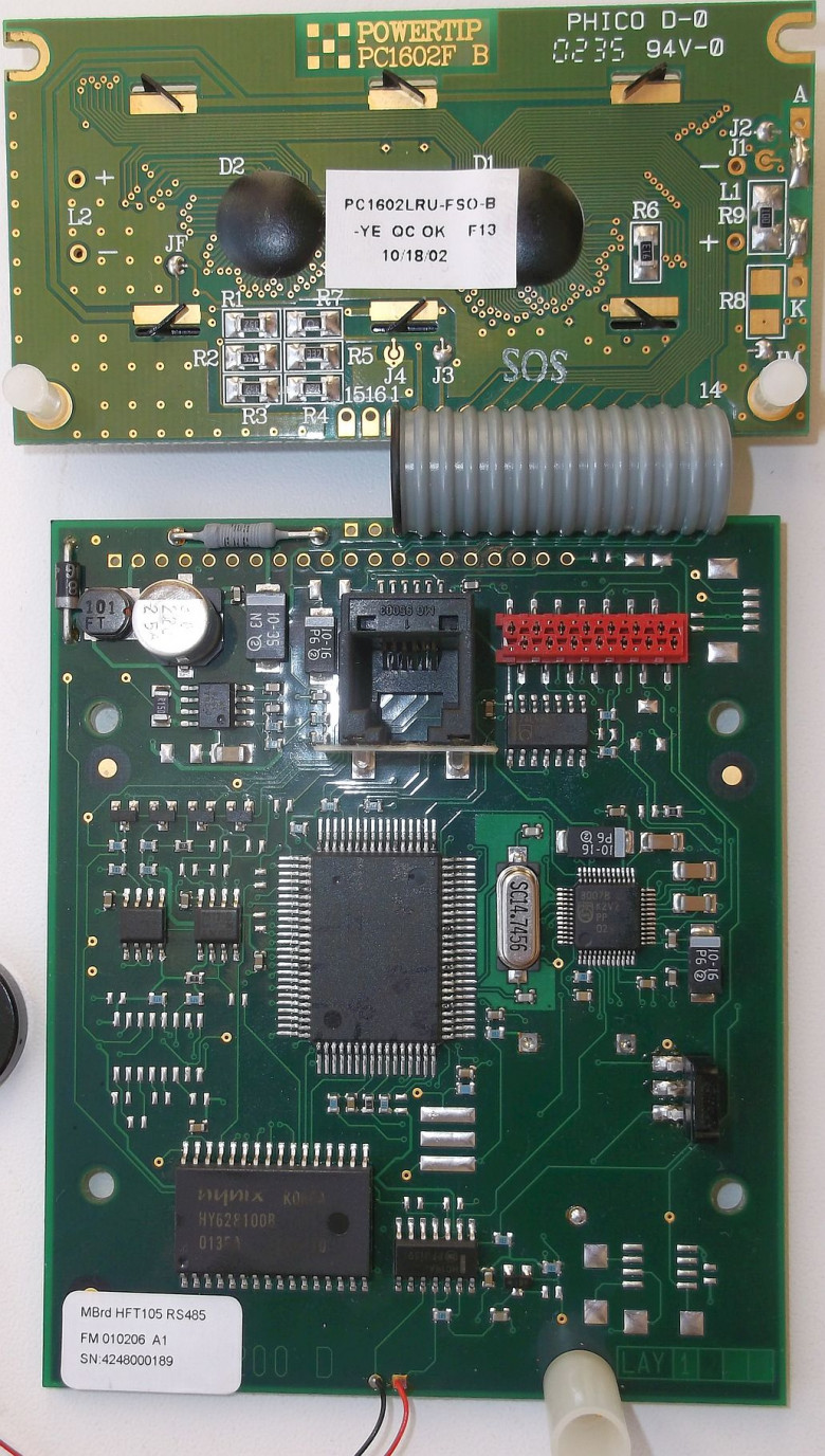
Close-up of the HFT105 terminal board.
So, the pin pad turned out to be assembled on the basis of a protected microcontroller from Dallas. This thing is very interesting - essentially it is an 8051-compatible MK, specially designed for such applications. This controller has no user ROM, all software is loaded into SRAM.
Here is its block diagram. It can be seen that to work with external memory, all data on the bus is also encrypted and also obfuscated (periodically the MK reads random values from memory to protect it from scanning the bus by a logic analyzer). There is also a hardware tamper input (Self-Destruct input), when activated, the keys and interrupt vectors are reset.
To protect against reverse engineering, there were even more secure versions of this chip available on order, which had a security circuit directly on the chip, which protects the chip from opening and examination with an electron microscope. The encryption algorithm used is DES with a key length of 64 bits; a proprietary encryption algorithm could also be provided at the customer’s discretion. The MK is equipped with a hardware random number generator (according to the datasheet, the principle is based on frequency deviations of the quartz and internal generator, which are measured by the controller), which is used to generate keys.
Here is a diagram of the safety circuit from the datasheet on the MK. As you can see, unencrypted data never leaves the secure area.
Well, it’s time to figure out how to work with such an MK.
So, in order to write some kind of firmware, you need an SDK. The standard set is libraries, a compiler and a loader.
The SDK for such an exotic controller can be found without any problems: it is included in Keil for the MCS-51 MK. Download Keil, open Device Database and install support for this MK.
Now it’s time to upload software to the controller. And here everything is very interesting: you don’t need any programmer for this.
As is clear from the description of the MK, its firmware is stored in SRAM, which is reset if the integrity of the circuit is violated. It is logical that the firmware should be loaded into an already assembled device.

If you pick out one of the rubber feet, you can see a cutout where two pins protruding from the resin are hidden. One of them is ground, the other is PROG. If they are closed, then when power is applied, the bootloader located in the mask ROM will be launched, the task of which is to place the program received via UART into SRAM. The jumper didn't fit on these pins, so I just stuffed some foil from a chewing gum wrapper there.
Now it’s the turn of the firmware software. There is such a utility as the Dallas Microcontroller Toolkit (MTK2). It is intended for uploading a HEX file with a program to a whole range of MKs from Dallas. Among all the others there is our copy.
The pin pad is connected to the terminal via the RS-422 interface. Inside, it is implemented on the basis of two RS-485 transceivers, one of which is always on for reception, and the other for transmission.

Of course, to connect the device to the computer, you need to solder an adapter. Its diagram in my case turned out like this:

It so happened that a month earlier I disassembled another terminal - Hypercom Optimum T4220. It was from its interface module that all the necessary components were borrowed - a microcircuit, a 6P6C connector and a cable from the pin pad. In principle, nothing prevents you from using two RS-485 transceivers, as is implemented in the pin pad.
Device diagrams from the nedoPC forum. Copied here just in case

So, we connect the device to the computer. Arduino traditionally acted as a USB-UART converter. We close the contacts and supply power.

Now open MTK2 and try to establish a connection with the bootloader. And it works!
Of course, if you turn on the power just like that, then nothing will happen - due to a dead battery, the original firmware has long been lost.
If you open the list of commands, you will notice that among them there is the ability to manage ports directly from the bootloader. To check, let's try to start the tweeter. Using the P command, we set the corresponding pin to a high level, and the terminal begins to beep continuously. Well, the circuit did not deceive us, HFT106 is indeed close to HFT105 in many ways.
The official procedure for downloading the firmware is as follows:
During these operations, the memory is cleared, after which the RNG generates a key (it is non-retrievable and cannot be read) with which the firmware is encrypted. If the execution of the bootloader program was not interrupted (that is, if the E command was not executed or if the MK was not reset), then it is also possible to read the contents of the RAM, which is used for verification.
After the program has been successfully uploaded, you need to set the protection flag with the Z command , blocking access to memory. From now on, its contents will be closed forever; the downloader or anything else from the outside will not be able to access it. This operation is irreversible; if this bit is set, then it can be reset either by completely clearing the memory, or by the U command , which resets the keys (which also leads to loss of information).
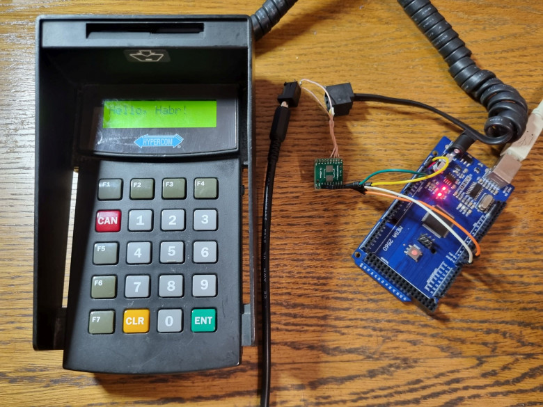
Well, time to write something for this device. Let's start, of course, with the classic microcontroller “Hello, world!” — from displaying text on the screen.
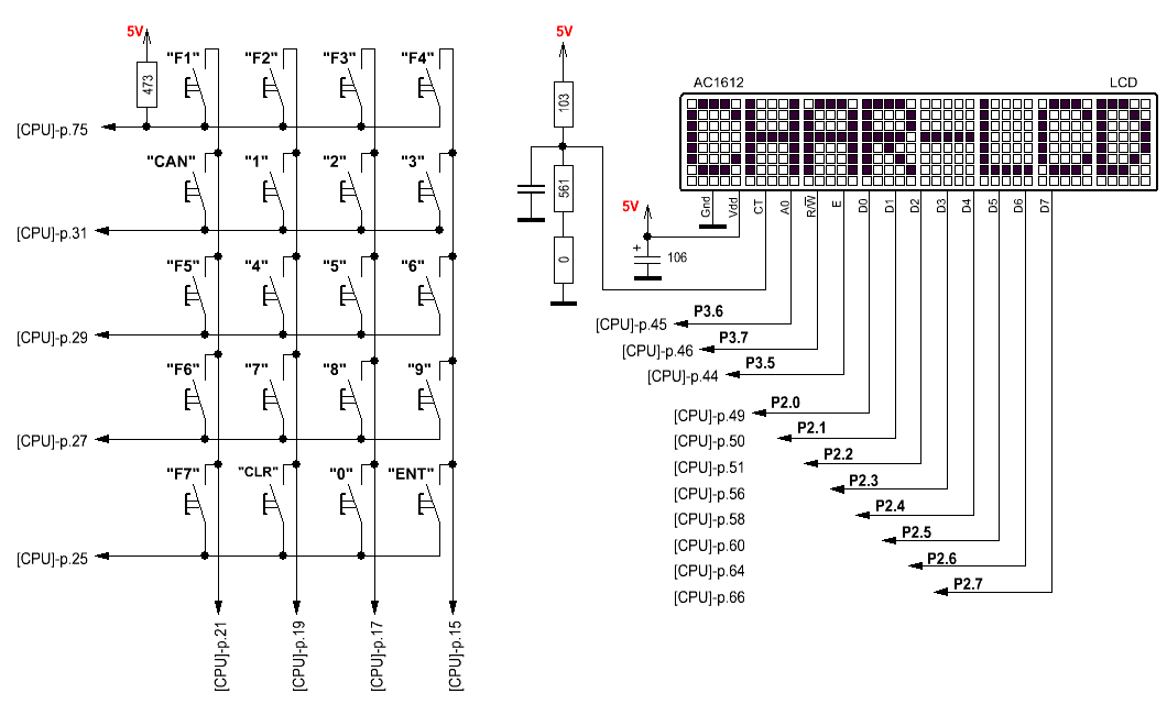
The display here operates in eight-bit mode, all of its data lines are connected to port P2. P3 is allocated for control lines. So, the test program turned out like this:
Initialization of the display is absolutely standard; I see no point in describing it in detail.
We assemble the project and in the folder with it we get a *.hex file with ready-made firmware.

Now open MTK2, select “Load SRAM” in the menu, select our firmware. Once the download is complete, send command E.
And, if everything was successful, something like the following will appear on the screen:

Well, everything is successful.
Well, where there is a display, there is a keyboard. I don’t have a smart card reader circuit, so this is the only peripheral that can still be launched. And the program turned out like this:
We run it, and here is the result:

Alas, I do not have any software or documentation for Hypercom pin pads or terminals. There is probably the least information on these terminals on the Internet.
As for payment functions (storing keys, working with cards), the microcontroller does not have hardware support for them. The DS5002FP was a general-purpose chip (and was intended, by the way, not only for payment terminals, but also for those areas where protection against reverse engineering was needed), so everything was implemented using defunct firmware.

Of the other terminals that worked on the basis of such a chip, I know of Castles CIT7000, for which I was even able to find an SDK. Alas, I don’t have the hardware itself.
Alas, now it is not possible to actually use the device for anything: the battery has long since run out, and it is not possible to change it without destroying the case. In fact, the lifespan of the device is limited by the battery charge, after which the firmware is depleted in memory only until the power is turned off. Nevertheless, it was very interesting to try to launch this rare copy.
So it goes.
Many of us already know that POS terminals and pin pads are usually assembled on the basis of custom chips, datasheets for which cannot be found. But, of course, this was not always the case. And I became interested: what if I try to find such an ancient terminal, reverse its circuit and write something for it, without having either an SDK or documentation?
So, in today’s article we’ll look at and figure out how to launch a rare pin-pad from the early 2000s. Along the way, we’ll look into the firmware of old secure microcontrollers and find out how they worked. As usual, there will be a lot of interesting things.
❯ The point is
Once upon a time I already wrote a post about how pin pads work and what is inside them.
If you take apart a typical pin pad released after the mid-2000s, then most likely all the microcircuits inside will be proprietary. This means that information about them is probably only available to the terminal developers themselves.
But in the best years everything was completely different. And now we’ll figure out how it was.
❯ Equipment overview
It so happened that the Hypercom HFT106 pin pad fell into my hands. The device is very old, dating back to the early 2000s. In appearance, it is also very different from the ones we are used to, resembling either a calculator or some kind of service device. The smart card slot is located at the rear and the card is inserted vertically.
Back side. Nothing interesting here, just a 6P6C port.
And here is an example of the terminal to which such a device was connected. This is the Hypercom T7PS, an ancient device with a Z80 processor. But we’ll talk about this instance sometime later.
❯ Internals
Of course, to find out what it is assembled on, the device must be disassembled.
Here this is very problematic - not only is it filled with resin, but also a metal bracket immersed in epoxy is welded to the lid. Because of this, non-destructive disassembly is not possible. This cover eventually had to be broken off.
Having finally unscrewed the lid, we see an area fenced off from the rest of the body space, filled with resin. You can see the battery in it, which, of course, has been dead for a long time.
Display, regular 1602.
Card reader module. One of the connectors contained a SAM card, the second was empty. I wonder why it is there at all, in a flooded case... On the same board there is a tamper switch.
SAM card. The reverse side had no markings.
❯ What's inside this pin pad?
Of course, the question of what this device is based on remains open. I had to Google it. Someone on the nedoPC forum has already disassembled a similar terminal. The model, however, was different, HFT105. After several hours of poking around with epoxy and studying photographs of the board, it was found that the HFT106 is essentially a more secure analogue of the HFT105. In terms of circuit design, they are absolutely identical.
Close-up of the HFT105 terminal board.
❯ DS5002FP
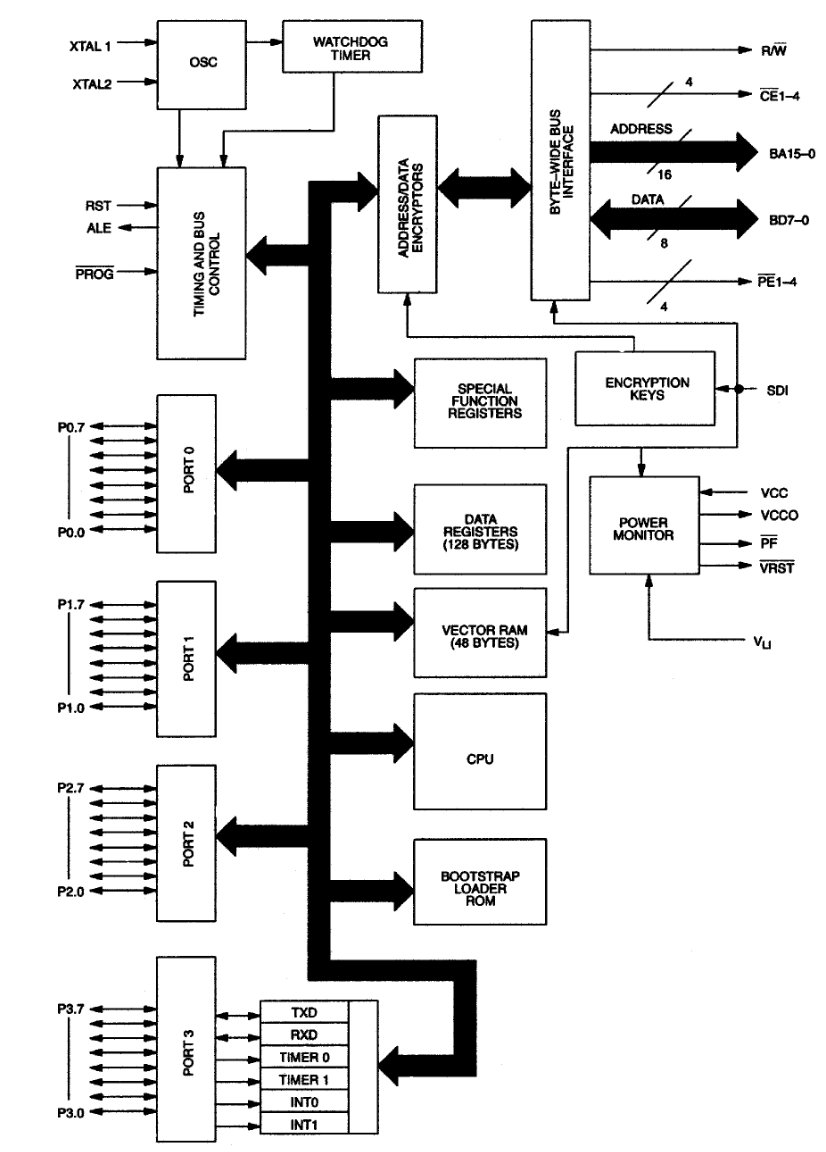
So, the pin pad turned out to be assembled on the basis of a protected microcontroller from Dallas. This thing is very interesting - essentially it is an 8051-compatible MK, specially designed for such applications. This controller has no user ROM, all software is loaded into SRAM.
Here is its block diagram. It can be seen that to work with external memory, all data on the bus is also encrypted and also obfuscated (periodically the MK reads random values from memory to protect it from scanning the bus by a logic analyzer). There is also a hardware tamper input (Self-Destruct input), when activated, the keys and interrupt vectors are reset.
To protect against reverse engineering, there were even more secure versions of this chip available on order, which had a security circuit directly on the chip, which protects the chip from opening and examination with an electron microscope. The encryption algorithm used is DES with a key length of 64 bits; a proprietary encryption algorithm could also be provided at the customer’s discretion. The MK is equipped with a hardware random number generator (according to the datasheet, the principle is based on frequency deviations of the quartz and internal generator, which are measured by the controller), which is used to generate keys.
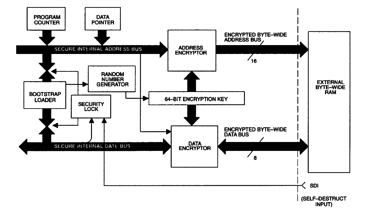
Here is a diagram of the safety circuit from the datasheet on the MK. As you can see, unencrypted data never leaves the secure area.
Well, it’s time to figure out how to work with such an MK.
❯Soft
So, in order to write some kind of firmware, you need an SDK. The standard set is libraries, a compiler and a loader.
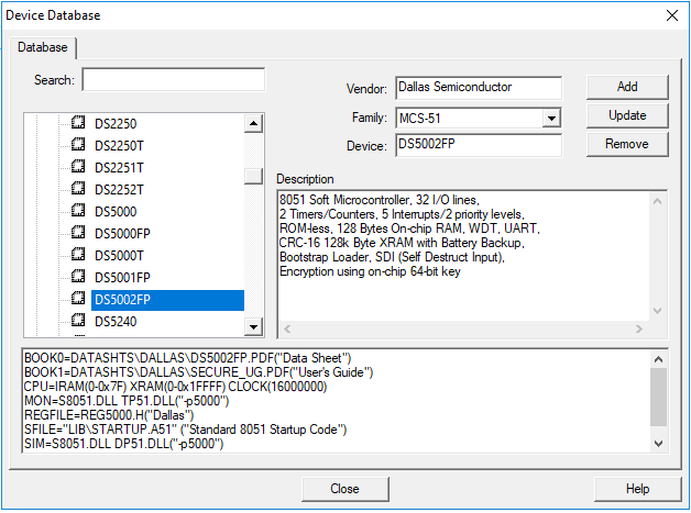
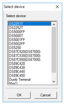
The SDK for such an exotic controller can be found without any problems: it is included in Keil for the MCS-51 MK. Download Keil, open Device Database and install support for this MK.
Now it’s time to upload software to the controller. And here everything is very interesting: you don’t need any programmer for this.
❯ MTK2
As is clear from the description of the MK, its firmware is stored in SRAM, which is reset if the integrity of the circuit is violated. It is logical that the firmware should be loaded into an already assembled device.
If you pick out one of the rubber feet, you can see a cutout where two pins protruding from the resin are hidden. One of them is ground, the other is PROG. If they are closed, then when power is applied, the bootloader located in the mask ROM will be launched, the task of which is to place the program received via UART into SRAM. The jumper didn't fit on these pins, so I just stuffed some foil from a chewing gum wrapper there.
Now it’s the turn of the firmware software. There is such a utility as the Dallas Microcontroller Toolkit (MTK2). It is intended for uploading a HEX file with a program to a whole range of MKs from Dallas. Among all the others there is our copy.
❯ Connection
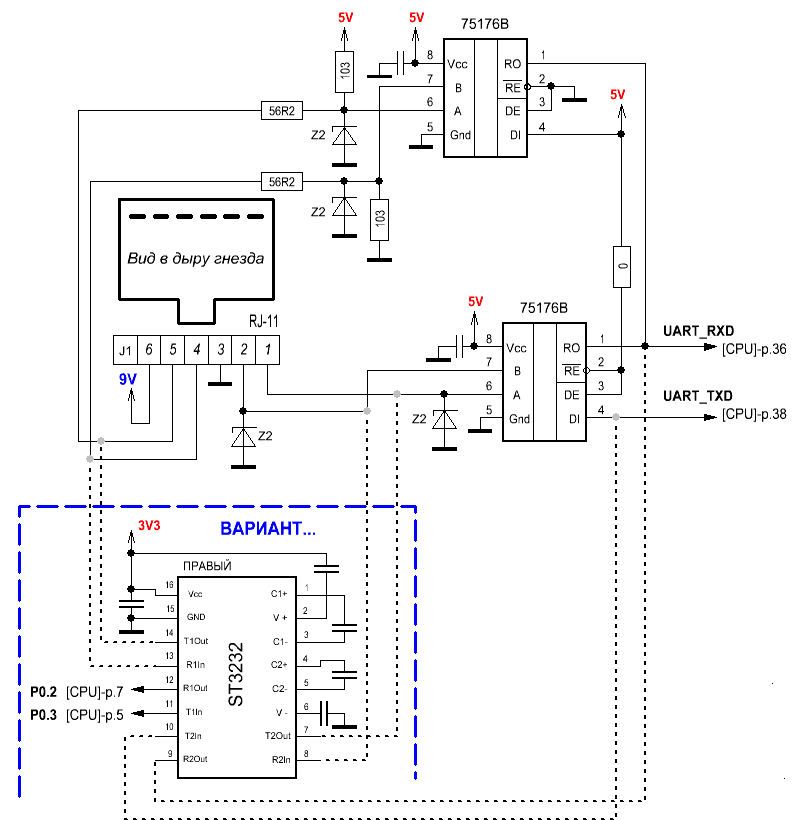
The pin pad is connected to the terminal via the RS-422 interface. Inside, it is implemented on the basis of two RS-485 transceivers, one of which is always on for reception, and the other for transmission.
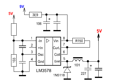
Of course, to connect the device to the computer, you need to solder an adapter. Its diagram in my case turned out like this:
It so happened that a month earlier I disassembled another terminal - Hypercom Optimum T4220. It was from its interface module that all the necessary components were borrowed - a microcircuit, a 6P6C connector and a cable from the pin pad. In principle, nothing prevents you from using two RS-485 transceivers, as is implemented in the pin pad.
Device diagrams from the nedoPC forum. Copied here just in case
❯ First start
So, we connect the device to the computer. Arduino traditionally acted as a USB-UART converter. We close the contacts and supply power.
Now open MTK2 and try to establish a connection with the bootloader. And it works!
Of course, if you turn on the power just like that, then nothing will happen - due to a dead battery, the original firmware has long been lost.
❯ Bootloader
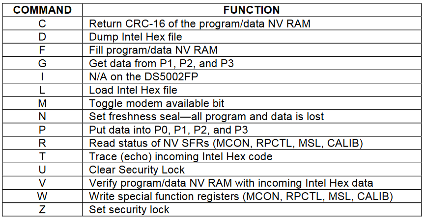
If you open the list of commands, you will notice that among them there is the ability to manage ports directly from the bootloader. To check, let's try to start the tweeter. Using the P command, we set the corresponding pin to a high level, and the terminal begins to beep continuously. Well, the circuit did not deceive us, HFT106 is indeed close to HFT105 in many ways.
The official procedure for downloading the firmware is as follows:
- F. Wipe SRAM.
- L. Fill in HEX.
- D. Read memory.
- V. Check that the entry is correct.
- C. Check CRC.
During these operations, the memory is cleared, after which the RNG generates a key (it is non-retrievable and cannot be read) with which the firmware is encrypted. If the execution of the bootloader program was not interrupted (that is, if the E command was not executed or if the MK was not reset), then it is also possible to read the contents of the RAM, which is used for verification.
After the program has been successfully uploaded, you need to set the protection flag with the Z command , blocking access to memory. From now on, its contents will be closed forever; the downloader or anything else from the outside will not be able to access it. This operation is irreversible; if this bit is set, then it can be reset either by completely clearing the memory, or by the U command , which resets the keys (which also leads to loss of information).
❯ We write the first program
Well, time to write something for this device. Let's start, of course, with the classic microcontroller “Hello, world!” — from displaying text on the screen.
The display here operates in eight-bit mode, all of its data lines are connected to port P2. P3 is allocated for control lines. So, the test program turned out like this:
Code:
#include <REG52.H>                /* special function register declarations   */
                                  /* for the intended 8051 derivative         */
#include <stdio.h>                /* prototype declarations for I/O functions */


#ifdef MONITOR51                         /* Debugging with Monitor-51 needs   */
char code reserve [3] _at_ 0x23;         /* space for serial interrupt if     */
#endif                                   /* Stop Exection with Serial Intr.   */
                                         /* is enabled                        */

/*------------------------------------------------
The main C function.  Program execution starts
here after stack initialization.
------------------------------------------------*/
void delay(void) {
unsigned long n;
    for(n = 0; n < 100; n++);;
}

void lcdSend(int isCommand, unsigned char toLCD) {
    P3 &= ~(1 << 7);
    if(isCommand == 0) P3 |= (1 << 6);
    else if(isCommand == 1) P3 &= ~(1 << 6);
    delay();
    P2 = toLCD;
    P3 |= (1 << 5);
    delay();
    P3 &= ~(1 << 5);
    delay();
}
void lcdCommand(unsigned char cmd) {
    lcdSend(1, cmd);
}

void lcdChar(const char chr) {
    lcdSend(0, chr);
}

void lcdString(const char* str) {
    while(*str != '\0') {
        lcdChar(*str);
        str++;
    }
}
void main (void) {
/*------------------------------------------------
Setup the serial port for 1200 baud at 16MHz.
------------------------------------------------*/
#ifndef MONITOR51
    SCON  = 0x50;                /* SCON: mode 1, 8-bit UART, enable rcvr      */
    TMOD |= 0x20;               /* TMOD: timer 1, mode 2, 8-bit reload        */
    TH1   = 221;                /* TH1:  reload value for 1200 baud @ 16MHz   */
    TR1   = 1;                  /* TR1:  timer 1 run                          */
    TI    = 1;                  /* TI:   set TI to send first char of UART    */
#endif

   lcdCommand(0x38);
   lcdCommand(0x01);
   lcdCommand(0x06);
   lcdCommand(0x0C);
   lcdCommand(0x80);
   lcdString("Hello, Habr!");
    while(1);;
}
Initialization of the display is absolutely standard; I see no point in describing it in detail.
We assemble the project and in the folder with it we get a *.hex file with ready-made firmware.
Now open MTK2, select “Load SRAM” in the menu, select our firmware. Once the download is complete, send command E.
And, if everything was successful, something like the following will appear on the screen:
Well, everything is successful.
❯ Keyboard
Well, where there is a display, there is a keyboard. I don’t have a smart card reader circuit, so this is the only peripheral that can still be launched. And the program turned out like this:
Code:
#include <REG52.H>                /* special function register declarations   */
                                  /* for the intended 8051 derivative         */
#include <stdio.h>                /* prototype declarations for I/O functions */

#ifdef MONITOR51                         /* Debugging with Monitor-51 needs   */
char code reserve [3] _at_ 0x23;         /* space for serial interrupt if     */
#endif                                   /* Stop Exection with Serial Intr.   */
                                         /* is enabled                        */

/*------------------------------------------------
The main C function.  Program execution starts
here after stack initialization.
------------------------------------------------*/
void delay(void) {
unsigned long n;
    for(n = 0; n < 100; n++);;
}
char s[16];
char symbols[4][4] = {{'E', '0', 'R', 'C'},
                     {'9', '8', '7', 'B'},
              {'6', '5', '4', 'A'},
              {'3', '2', '1', 'Z'}};
char symbolsP0[4] =  {'L', 'K', 'J', 'I'};
void lcdSend(int isCommand, unsigned char toLCD) {
    P3 &= ~(1 << 7);
    if(isCommand == 0) P3 |= (1 << 6);
    else if(isCommand == 1) P3 &= ~(1 << 6);
    delay();
    P2 = toLCD;
    P3 |= (1 << 5);
    delay();
    P3 &= ~(1 << 5);
    delay();
}
void lcdCommand(unsigned char cmd) {
    lcdSend(1, cmd);
}

void lcdChar(const char chr) {
    lcdSend(0, chr);
}

void lcdString(const char* str) {
   while(*str != '\0') { //*str != '\0'
        lcdChar(*str);
        str++;
    }
}
void main (void) {
   int n1, i, j, k;
   lcdCommand(0x38);
   lcdCommand(0x01);
   lcdCommand(0x06);
   lcdCommand(0x0C);
    while(1) {
        P1 = 0x0F;
        P0 |= (1 << 7);
        for(i = 4; i < 8; i++) {
        for(j = 4; j < 8; j++) P1 |= (1 << j);
        P1 &= ~(1 << i);
        for(k = 0; k < 4; k++) {
            if(((P1 >> k) & 1) == 0 ) {
                P3 &= ~(1 << 4);
                n1 = P1;
                sprintf(s, "%X", n1);
                lcdCommand(0x80);
                lcdString("Scanc0de: ");
                lcdString(s);
                lcdCommand(0xC0);
                lcdString("Key: ");
                lcdChar(symbols[i-4][k]);
                for(j = 0; j < 30; j++)    delay();
            }
            else {
                P3 |= (1 << 4);
            }
        }
    }
        P0 &= ~(1 << 7);
        for(i = 0; i < 4; i++) {
            if(((P1 >> i) & 1) == 0 ) {
                P3 &= ~(1 << 4);
                n1 = P1;
                sprintf(s, "%X", n1);
                lcdCommand(0x80);
                lcdString("Scanc0de: ");
                lcdString(s);
                lcdCommand(0xC0);
                lcdString("Key: ");
                lcdChar(symbolsP0[i]);
                for(j = 0; j < 30; j++)    delay();
            }
            else {
                P3 |= (1 << 4);
            }
    }
}
}
We run it, and here is the result:
❯ What about banking functions?
Alas, I do not have any software or documentation for Hypercom pin pads or terminals. There is probably the least information on these terminals on the Internet.
As for payment functions (storing keys, working with cards), the microcontroller does not have hardware support for them. The DS5002FP was a general-purpose chip (and was intended, by the way, not only for payment terminals, but also for those areas where protection against reverse engineering was needed), so everything was implemented using defunct firmware.
Of the other terminals that worked on the basis of such a chip, I know of Castles CIT7000, for which I was even able to find an SDK. Alas, I don’t have the hardware itself.
❯ Something like that
Alas, now it is not possible to actually use the device for anything: the battery has long since run out, and it is not possible to change it without destroying the case. In fact, the lifespan of the device is limited by the battery charge, after which the firmware is depleted in memory only until the power is turned off. Nevertheless, it was very interesting to try to launch this rare copy.
So it goes.