Man
Professional
- Messages
- 3,070
- Reaction score
- 606
- Points
- 113
Studying the structure of network protocols will help you to understand their operation and functions in more depth. In this article, we will analyze a small fragment of network traffic and draw a hypothetical network diagram based on the obtained data.
I dumped network traffic on my lab setup using Capture Filtering in Wireshark with some conditions. Here's what came out of it.
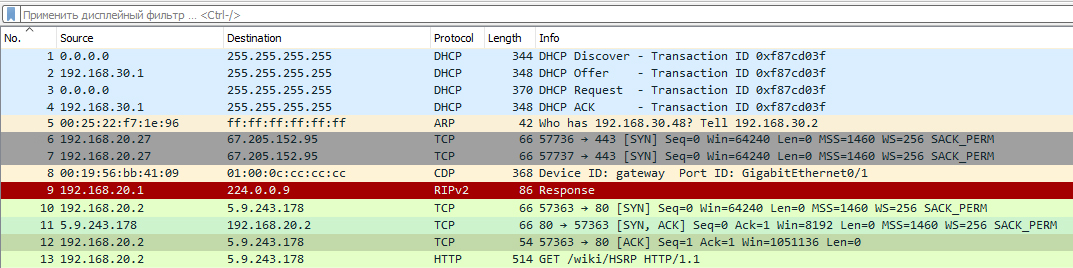
We will unpack each captured packet in order and search the encapsulated data for the information we are interested in about the original network diagram. We will then display this information graphically (for this we will use the diagrams.net resource).
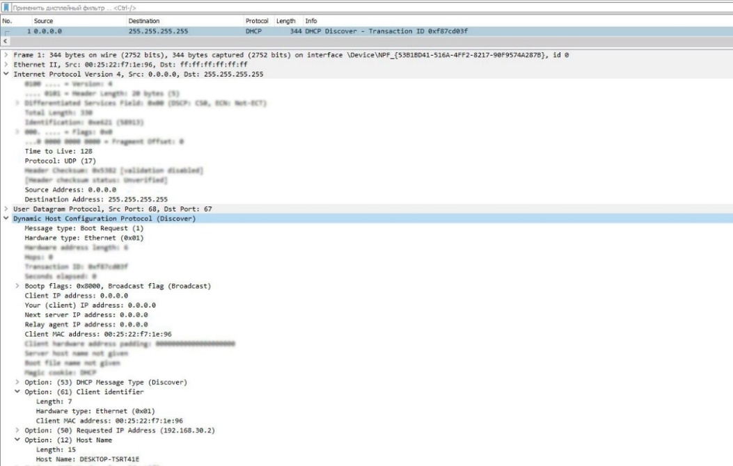
The MAC address of the client device is immediately noticeable. We don't know the network address of this device yet, because it hasn't received it yet, and the destination addresses are broadcast.
Moving on. You may have noticed the IP address 192.168.30.2in the header section 50 DHCP. This means that the client is requesting this IP address, as it may have received it before. But for now, we will not display it on the diagram and wait for the final response from the DHCP server.
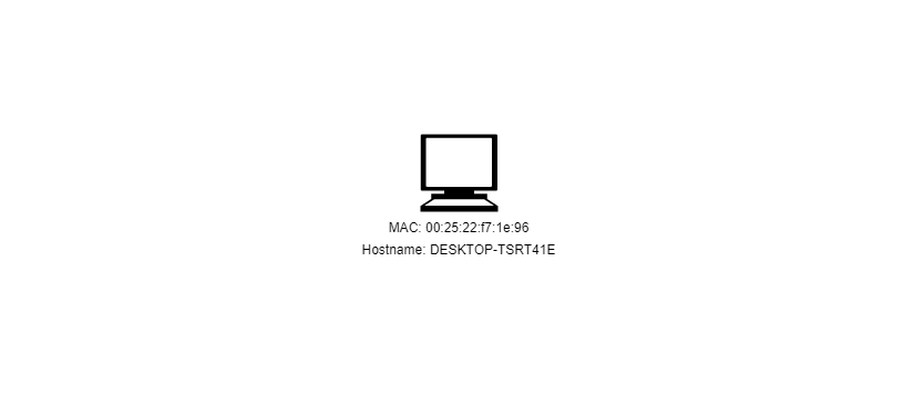
And the last thing we are interested in in this package is the option 12 DHCP. Here the name of the device is displayed. Now let's transfer the obtained data to the diagram.
The next DHCP Offer packet is a response from the server to the client's message, offering possible network parameters.
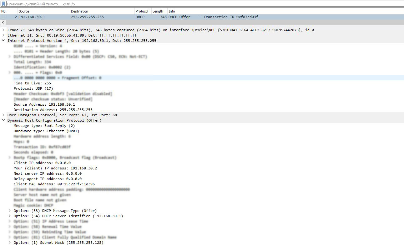
As we can see, the DHCP server responded to the client's request with an IP address 192.168.30.1and a MAC address 00:19:56:bb:41:09. It offered the client an IP address 192.168.30.2(by the way, the one the client requested, the Your IP address field) and a network mask 255.255.255.128. Great, let's add new data to the diagram.

I will color new elements red for clarity.
I would also like to draw attention to the Time to Live field of the IPv4 header of this message.
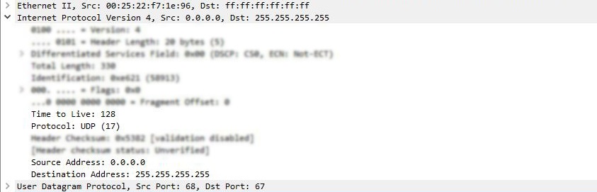
TTL is a value that determines the time to live of a packet. This value is decremented by one each time the packet passes through a routing device on its way to its destination.
The fact is that different operating systems have their own default TTL values.
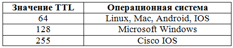
Since DHCP Requestthe TTL value in the client message is 128, we can assume that this is a Windows device.
(c) xakep.ru
I dumped network traffic on my lab setup using Capture Filtering in Wireshark with some conditions. Here's what came out of it.
We will unpack each captured packet in order and search the encapsulated data for the information we are interested in about the original network diagram. We will then display this information graphically (for this we will use the diagrams.net resource).
LEARN THE CHANNEL AND NETWORK ADDRESSES OF THE FIRST DEVICES
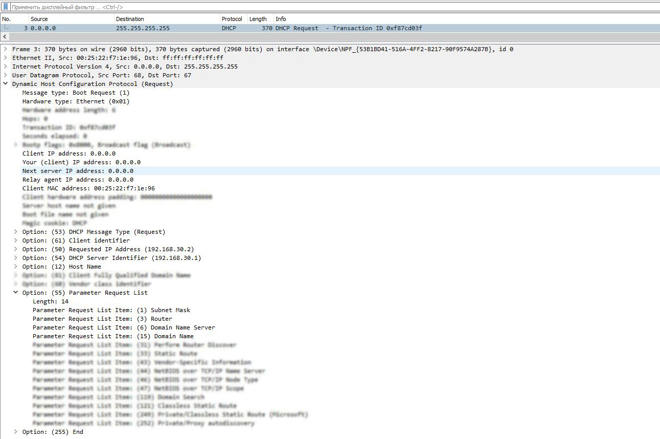
From the first four packets it is immediately clear that a certain device receives an IP address and other network parameters via DHCP. Let's open the first packet.
The MAC address of the client device is immediately noticeable. We don't know the network address of this device yet, because it hasn't received it yet, and the destination addresses are broadcast.
Moving on. You may have noticed the IP address 192.168.30.2in the header section 50 DHCP. This means that the client is requesting this IP address, as it may have received it before. But for now, we will not display it on the diagram and wait for the final response from the DHCP server.
And the last thing we are interested in in this package is the option 12 DHCP. Here the name of the device is displayed. Now let's transfer the obtained data to the diagram.
The next DHCP Offer packet is a response from the server to the client's message, offering possible network parameters.
As we can see, the DHCP server responded to the client's request with an IP address 192.168.30.1and a MAC address 00:19:56:bb:41:09. It offered the client an IP address 192.168.30.2(by the way, the one the client requested, the Your IP address field) and a network mask 255.255.255.128. Great, let's add new data to the diagram.
I will color new elements red for clarity.
MICROSOFT WINDOWS AND CISCO IOS, OR WHAT DOES TTL HAVE TO DO WITH IT?
The message DHCP Requestdoes not contain any new information, except that in the option 55the client requests additional parameters from the DHCP server: network mask, gateway address, DNS server and domain name.
I would also like to draw attention to the Time to Live field of the IPv4 header of this message.
TTL is a value that determines the time to live of a packet. This value is decremented by one each time the packet passes through a routing device on its way to its destination.
The fact is that different operating systems have their own default TTL values.
Since DHCP Requestthe TTL value in the client message is 128, we can assume that this is a Windows device.
(c) xakep.ru