Lord777
Professional
- Messages
- 2,579
- Reaction score
- 1,493
- Points
- 113
Greetings to all!
The fact that magnetic cards will soon go down in history forever has been talked about for several years. However, although they are gradually being replaced by other technologies (for example, RFID, ISO7816), they are not even going to disappear completely yet.
So, in this article, we'll talk about how data recording works on magnetic stripe cards, find out what format information is stored there, find out how the reader and encoder work, and, of course, many other interesting things.
On the open spaces you can find a huge amount of materials about the device and the principle of operation of RFID cards. There is much less information about magnetic cards. There are reasons for this: magnetic stripe readers are relatively expensive, very little data can fit on the card, and the technology itself is hopelessly outdated. But, as for me, it will be very interesting to consider such equipment in detail. And if so, let's go!
Traditionally, such a card is an ordinary plastic card of the ISO7810 standard, on the reverse side of which a magnetic stripe is applied with the smallest ferromagnet particles. In the experimental samples, sections of magnetic tape were used.
According to the field strength required for rewriting, maps are divided into high-coercivity and low-coercivity ones. Currently, the first option is mainly used, which has much greater resistance to wear and external magnetic fields, while low-coercive strips are demagnetized from contact even with low-power magnetsor simply from a sideways glance.
We'll talk about the sensitivity to magnetic fields of high-coercivity maps later.
All magnetic stripe cards use F/2F encoding to record data. In it, the logical unit corresponds to the signal frequency that is twice as high as that for zero. The transition is indicated by changing the polarity when the card is magnetized. The reason for using this encoding principle is very simple — you can significantly simplify the device for reading, since the result will not depend on the speed of rolling the card through it. Other encoding methods would require the installation of an electric drive to automatically capture and move the card, or a mechanically connected roller to the encoder to control the speed.
The map itself has three tracks, the first is seven — bit encoded, the second and third are five-bit encoded. Directly for data, six and four bits are used, respectively, and the highest bit in the code of each character is reserved for parity. The low — order bits are first written to the magnetic strip, then the high-order bits are written to the magnetic strip.
At the beginning and end of the track there are symbols indicating the beginning and end of the sequence. After the stop symbol, a control value is written, which is a sequential XOR of all characters on the track, also supplemented with its own parity bit.
Thus, the algorithm for reading the card is as follows::
In addition to the encoding, there is also a standard that defines what exactly is recorded on the magnetic strip. However, in systems other than payment systems (for example, electronic passes, discount cards, gift cards, and club cards), any arbitrary information can be recorded.
Let's take a closer look at bank cards. Here is an example of a dump of the second track:
;4034351574462072=2402121111946800?
So, the numbers before the separator (the " = " symbol) are PAN (Primary Account Number), actually, the card number itself. I hasten to assure you that these data were created using the service for generating "left" card numbers and have nothing to do with the real map.
The next group of four digits is the expiration date in YYMM format. Next is the Service code. This is a three-digit number that allows you to set a number of restrictions, for example, to prohibit the use of a magnetic stripe (when you try to roll such a card, the requirement to use a chip will light up on the terminal screen). The Service code values are described in more detail here. By tradition, all mentioned links will be duplicated at the end of the post.
Then there are five more digits-PVV (PIN Verification Value). The first digit is the so-called PIN Verification Key Index (PVKI) - the identifier (index) of the key that was used to calculate a specific PVV value. It usually ranges from 1 to 6, meaning that the issuer can use up to six different keys to calculate / verify the PVV. The remaining four digits represent directly the PVV value. As you might guess, this number is used to verify the PIN of the card.
The last group of digits in the sequence is CVV-1/CVC-1. This code is used for authorization using a magnetic stripe. It should not be confused with CVV-2 / CVC-2, which is printed on the back of the card next to the signature area.
Time to go to the hardware review. I had two Posiflex MR-2000U magnetic card readers. My instance is designed to read the first and second tracks and has a USB connection interface.
Most of these readers emulate the keyboard by simply outputting track data, optionally adding a newline at the end. This allows you to record map data even in Excel.
Let's analyze the instance. Two chips are clearly visible on the board — one is responsible for F/2F decoding, the other for processing data and sending it via USB. Jumpers set the mode of operation, for example, you can enable or disable reading one or more tracks, or display the start and end characters of each track.
And here is the reading node itself. The head is fixed in a plastic chassis, on which there is also a handkerchief with operational amplifiers. The same modules are also used in other Posiflex products, such as programmable cash register keyboards.
Magnetic head separately. It is from the Ingenico 5100 POS terminal. Its three tracks are clearly visible.
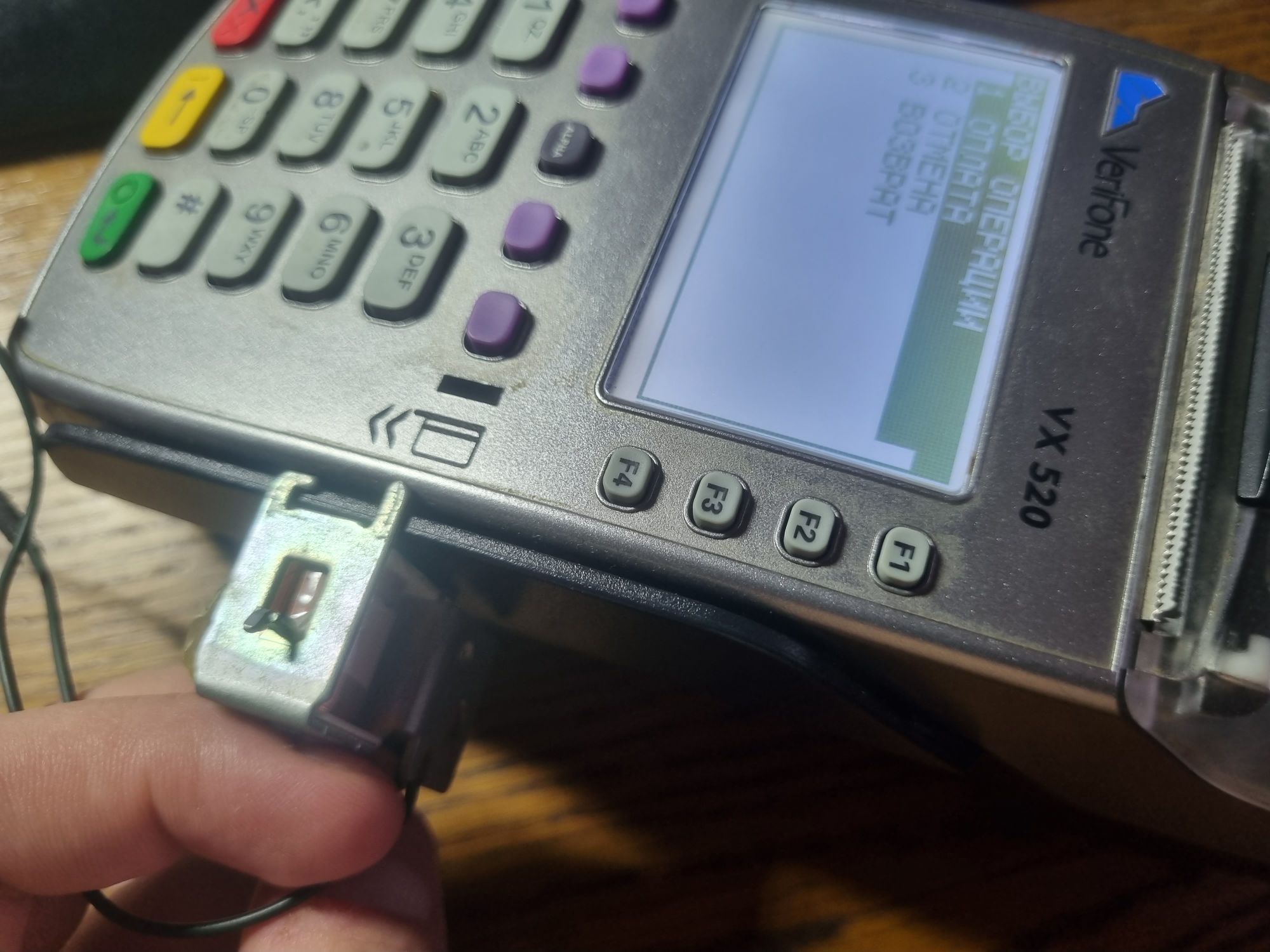
And here's the other head. These were used in VeriFone VX510 terminals.
We figured out how the factory reader works. Now let's try to build our own version.
I still have the magnetic head and the MRD531B-LQ decoder chip from the dead VX510. Without any problems, having found the documentation for this chip (just Googling "MRD531 PDF"), I assembled a typical power-on circuit on a breadboard.

A short search for some example of working with a magnetic reader on the MK led me to a library for connecting such a reader to the Arduino.
The connection interface is extremely simple: CLS output for monitoring the map availability and traditional DATA/CLK for each of the tracks.
As it turned out later, the scheme is very oaky and works even with components that are significantly far from the recommended nominal value.
There are also no significant requirements for the head, if there is no one from the reader, even a copy from a cassette recorder will do.
If you don't even have an F/2F decoder, but you want to use a reader, you can build this circuit yourself.
Well, let's move on to the most interesting part — how to record on magnetic cards.
Such a device, as you might guess, is much more complex and expensive than a reader. On our secondary market, a typical encoder costs about eight thousand rubles (I wonder where this price comes from?) when the cost of the reader is ten times less, which is too expensive for me.
However, I was lucky enough to get a copy. It is called MSR206U. The most advanced model-writes and reads all three tracks, and supports high-precision maps. The device is in good condition, with a power supply (twenty-four volts), but without a USB cable. Well, a great reason to disassemble the device, since I did not find the pinout of the 8P8C connector.
So, the device is somewhat similar to a reader, although about one and a half times larger than usual. Front slot for magnetic card, three indicator LEDs, model designation.

Rubber feet on the bottom, a sticker indicating the model, four screws, one of which is sealed with a warranty seal. I had to tear it off.
And here's the fee. Powerful resistors, two relays, a microcontroller, and a ROM are clearly visible. The recording head driver deserves special mention: it is made on three L293D H-bridges (presumably, one for each track). The USB interface is implemented on the basis of the USB-TTL Prolific PL-2303HX converter chip.
The pinout, by the way, turned out to be like this:
The main part. A small plume (barely visible next to the yellow tape pasted on) from the reader head. A blue wire harness leads to the recording system. The remaining wires lead to an optocoupler that detects when the card is inserted, and indicator LEDs. A black plastic part with colored wires leading to it is an encoder.
From a different angle. The read and write heads are clearly visible. An optocoupler is neatly fixed above the recording unit in Chinese.
And here's the encoder. On the shaft it has a rubber roller that rotates when the card is rolled and serves to track its position.
In addition to the encoder, I also got maps. If that's the case, let's try to write something down.

We put the software supplied with the encoder, 206DDX51. Launching it.
In the settings, specify the COM port, select a high-coercivity card type, enter some data, and click the record button. The yellow LED on the encoder lights up. Now we roll the card, and if recording and verification are successful, the yellow LED will go out, and the green LED will light up. That's it, the map was successfully recorded. We roll it in the reader and make sure that everything is being read successfully.
Of course, magnetic cards can be emulated. Many of us even remember the MST feature in some Samsung phones. And now we will try to deal with card emulation and assemble a device for this purpose from just three parts (I already remembered the post of comrade dlinyj about the RFID emulator from three parts). This time, however, everything will be much easier.
There is such a project as MagSpoof. At one time, it was even mentioned here, but all this did not arouse much interest then.
MagSpoof is a magnetic card emulator consisting of a coil, the field of which will be registered by the reader head, the ATtiny85 microcontroller, and the L293D H-bridge already mentioned here.
The project code was written for the Arduino platform and can be run with minimal changes (just change the leg numbers) on almost any board. I just happened to have a Mega handy. This is where we will collect all this stuff. I didn't use the circuit board this time, but placed everything on a solderless breadboard.
I didn't have a goal to make a fully autonomous device, so I started from what I had. I didn't want to wind up the reel for a device that I would play with for ten minutes and then sort out, so I had to look for something suitable in the bins. By the way, a box with parts from old printers caught my eye. Stepper motors, guides, optocouplers and HVPS boards will be left for some other experiments, but the solenoid, from among those that are in the exciting mechanism of laser printers, will be just right.
We disconnect the moving part from it (carefully, so as not to lose the spring, because we, after all, then put it back), and, in general, that's all.
Putting together the diagram. The ENABLE, A and B pins of the L293D are connected to the digital pins of the MK, logic power is connected to five volts, load power is connected to twelve (in general, the solenoid is designed for twenty — four volts, but in this experience I would not supply so much, since you can also magnetize the head itself). Now fill in your map dump and fill in the sketch. Everything, you can try.
We press the coil to the reader, press the button... and everything works successfully the first time, our card number appears in the open Notepad.
Well, where there is a reader, there is a POS-terminal. And it works great on him, too. Everything is as we wanted it to be.
The principle of operation of this emulator is extremely simple — the program calculates the parity and reference value for a given track, and then reproduces it on a reel using an H-bridge that allows you to change the polarity. In theory, if you connect a recording head and an encoder, and connect the current supply not to fixed timings, but to signals from the encoder, you can even create a device for recording cards.
As a couple of experiments have shown, highly coercive cards are very resistant to being near metal objects and even the short-term presence of a magnet.
Plastic and ferrite magnets could not affect the magnetic stripe at all. It was possible to erase the data only with a neodymium magnet, passing it along the strip.
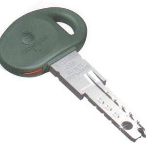
So it is still not worth carrying magnetic cards in wallets with magnetic fasteners or with some keys (for example, Mottura produced locks whose keys contained neodymium magnets).
Also, do not forget about the banal wear and tear of the card. At one time, the Maestro magnetic cards that were produced were literally stratified from frequent use, of course, while ceasing to be readable.
In the banking sector, magnetic cards are already going down in history. The largest payment systems have already announced that they will stop issuing magnetic stripe cards in just five years.
And even in other areas where such cards were used, RFID is gradually taking its toll.
Of course, RFID or smart cards are now much easier and cheaper to use. However, I am quite sure that all these materials will be useful to someone.
The fact that magnetic cards will soon go down in history forever has been talked about for several years. However, although they are gradually being replaced by other technologies (for example, RFID, ISO7816), they are not even going to disappear completely yet.
So, in this article, we'll talk about how data recording works on magnetic stripe cards, find out what format information is stored there, find out how the reader and encoder work, and, of course, many other interesting things.
The bottom line is
On the open spaces you can find a huge amount of materials about the device and the principle of operation of RFID cards. There is much less information about magnetic cards. There are reasons for this: magnetic stripe readers are relatively expensive, very little data can fit on the card, and the technology itself is hopelessly outdated. But, as for me, it will be very interesting to consider such equipment in detail. And if so, let's go!
Card Device
Traditionally, such a card is an ordinary plastic card of the ISO7810 standard, on the reverse side of which a magnetic stripe is applied with the smallest ferromagnet particles. In the experimental samples, sections of magnetic tape were used.
According to the field strength required for rewriting, maps are divided into high-coercivity and low-coercivity ones. Currently, the first option is mainly used, which has much greater resistance to wear and external magnetic fields, while low-coercive strips are demagnetized from contact even with low-power magnets
We'll talk about the sensitivity to magnetic fields of high-coercivity maps later.
A little bit about coding
All magnetic stripe cards use F/2F encoding to record data. In it, the logical unit corresponds to the signal frequency that is twice as high as that for zero. The transition is indicated by changing the polarity when the card is magnetized. The reason for using this encoding principle is very simple — you can significantly simplify the device for reading, since the result will not depend on the speed of rolling the card through it. Other encoding methods would require the installation of an electric drive to automatically capture and move the card, or a mechanically connected roller to the encoder to control the speed.
The map itself has three tracks, the first is seven — bit encoded, the second and third are five-bit encoded. Directly for data, six and four bits are used, respectively, and the highest bit in the code of each character is reserved for parity. The low — order bits are first written to the magnetic strip, then the high-order bits are written to the magnetic strip.
At the beginning and end of the track there are symbols indicating the beginning and end of the sequence. After the stop symbol, a control value is written, which is a sequential XOR of all characters on the track, also supplemented with its own parity bit.
Thus, the algorithm for reading the card is as follows::
- We get a string of bits from the decoder. Almost nowhere do they connect the magnetic head directly to the controller, most often they use special F/2F decoder chips that send almost ready-made data;
- We determine the beginning and end of the received data (by searching for start and stop characters);
- We read the characters according to the encoding, and check the parity of each read character;
- Calculating and checking the control number;
- If no errors were found, output the finished string.
Bank cards
In addition to the encoding, there is also a standard that defines what exactly is recorded on the magnetic strip. However, in systems other than payment systems (for example, electronic passes, discount cards, gift cards, and club cards), any arbitrary information can be recorded.
Let's take a closer look at bank cards. Here is an example of a dump of the second track:
;4034351574462072=2402121111946800?
So, the numbers before the separator (the " = " symbol) are PAN (Primary Account Number), actually, the card number itself. I hasten to assure you that these data were created using the service for generating "left" card numbers and have nothing to do with the real map.
The next group of four digits is the expiration date in YYMM format. Next is the Service code. This is a three-digit number that allows you to set a number of restrictions, for example, to prohibit the use of a magnetic stripe (when you try to roll such a card, the requirement to use a chip will light up on the terminal screen). The Service code values are described in more detail here. By tradition, all mentioned links will be duplicated at the end of the post.
Then there are five more digits-PVV (PIN Verification Value). The first digit is the so-called PIN Verification Key Index (PVKI) - the identifier (index) of the key that was used to calculate a specific PVV value. It usually ranges from 1 to 6, meaning that the issuer can use up to six different keys to calculate / verify the PVV. The remaining four digits represent directly the PVV value. As you might guess, this number is used to verify the PIN of the card.
The last group of digits in the sequence is CVV-1/CVC-1. This code is used for authorization using a magnetic stripe. It should not be confused with CVV-2 / CVC-2, which is printed on the back of the card next to the signature area.
Reader
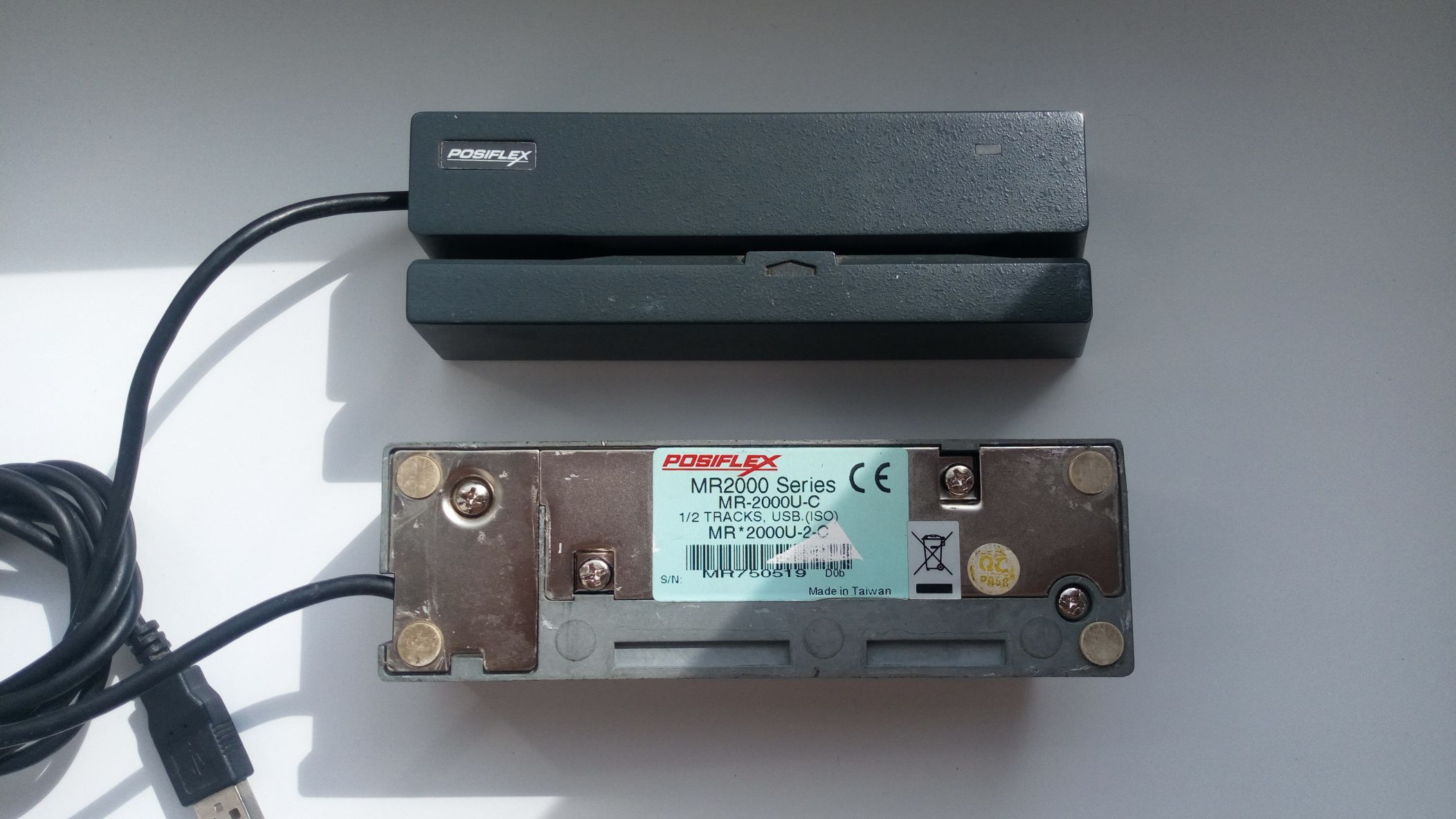
Time to go to the hardware review. I had two Posiflex MR-2000U magnetic card readers. My instance is designed to read the first and second tracks and has a USB connection interface.
Most of these readers emulate the keyboard by simply outputting track data, optionally adding a newline at the end. This allows you to record map data even in Excel.
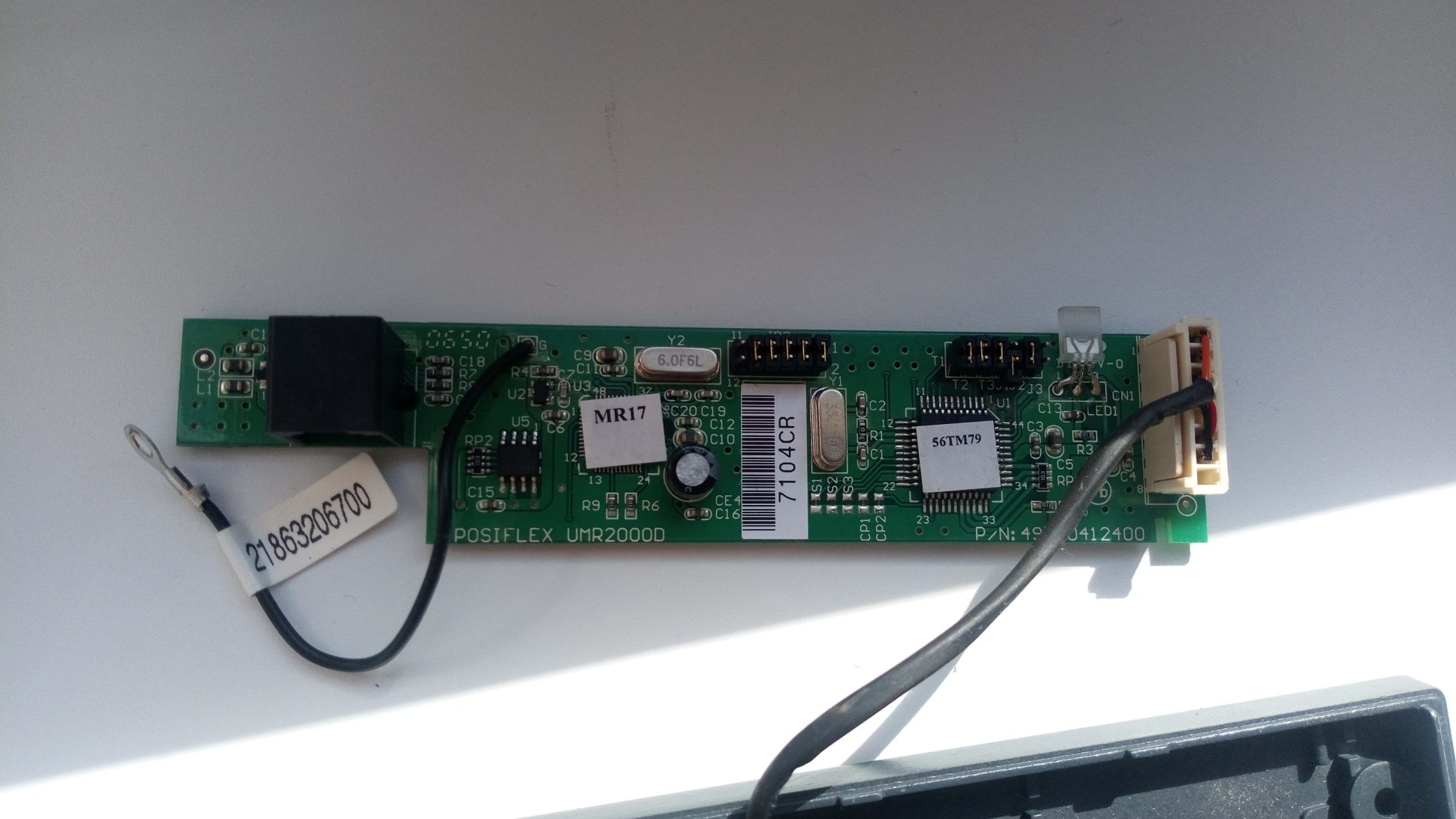
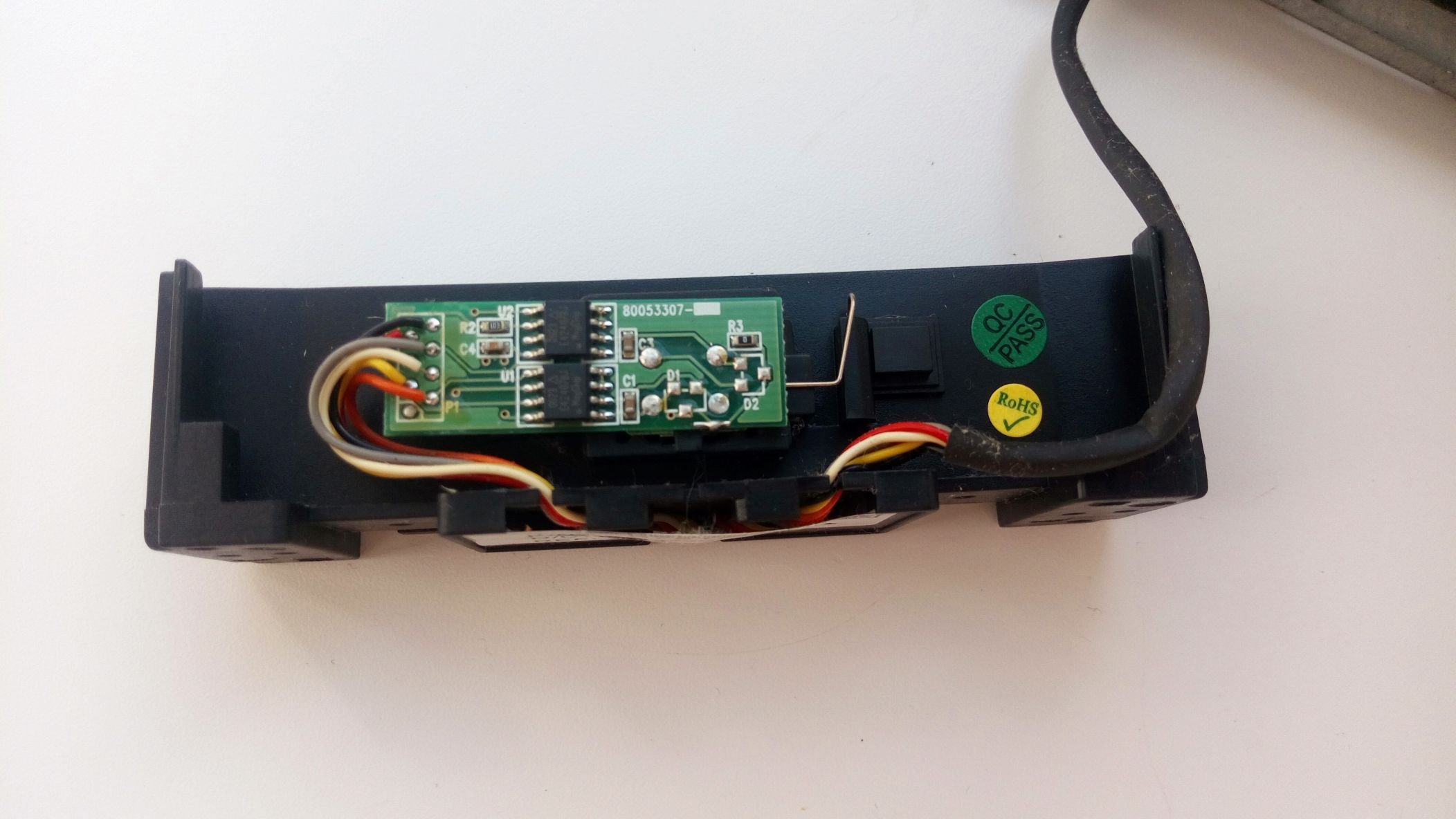
Let's analyze the instance. Two chips are clearly visible on the board — one is responsible for F/2F decoding, the other for processing data and sending it via USB. Jumpers set the mode of operation, for example, you can enable or disable reading one or more tracks, or display the start and end characters of each track.
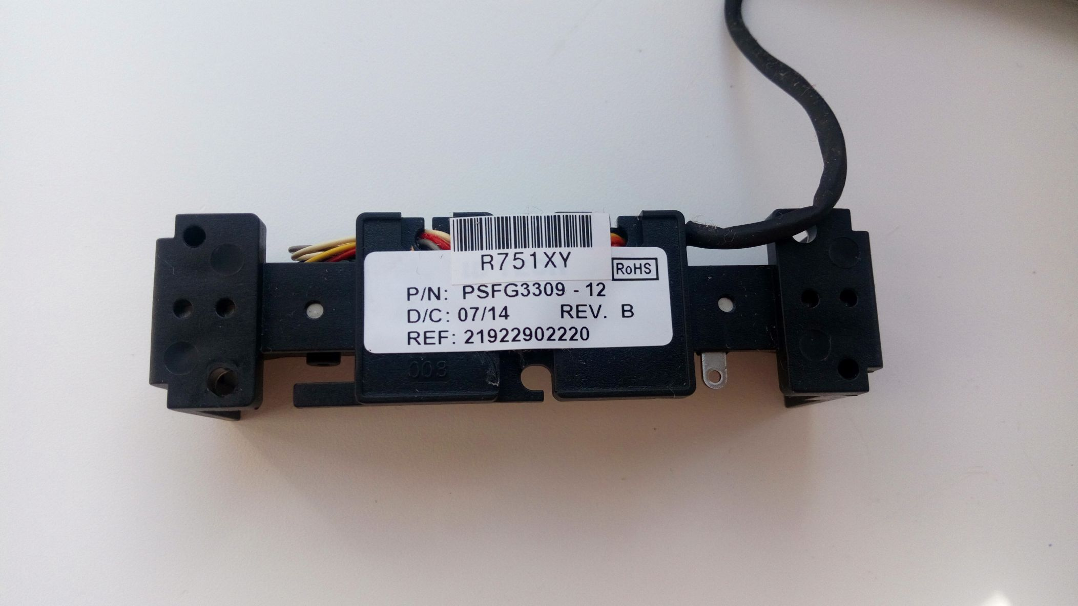
And here is the reading node itself. The head is fixed in a plastic chassis, on which there is also a handkerchief with operational amplifiers. The same modules are also used in other Posiflex products, such as programmable cash register keyboards.
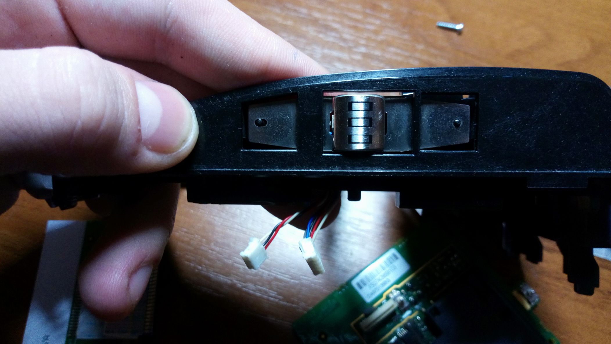
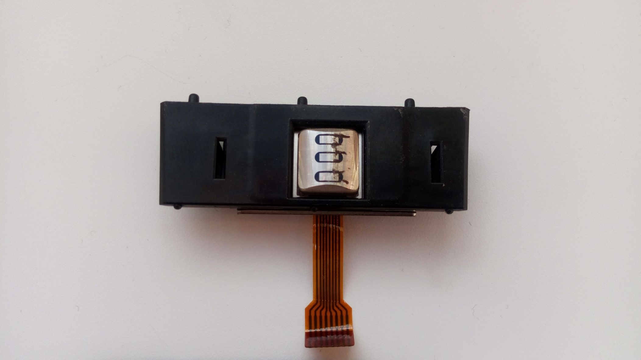
Magnetic head separately. It is from the Ingenico 5100 POS terminal. Its three tracks are clearly visible.
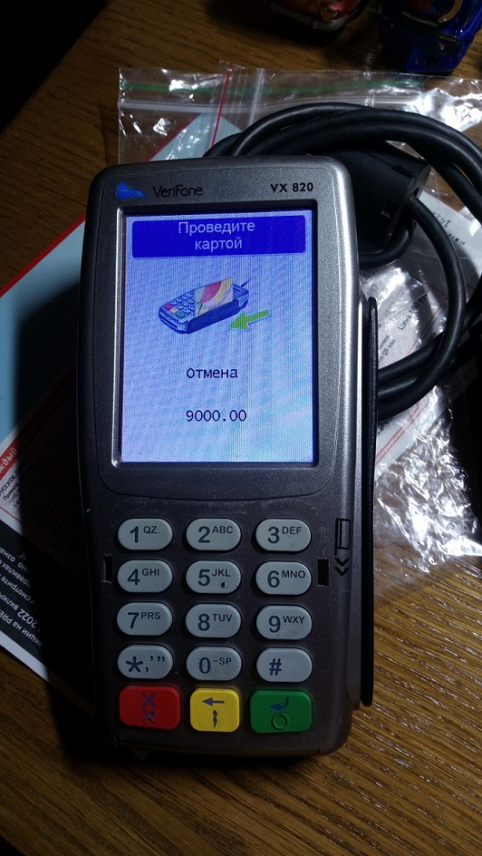
And here's the other head. These were used in VeriFone VX510 terminals.
We build the reader ourselves
We figured out how the factory reader works. Now let's try to build our own version.
I still have the magnetic head and the MRD531B-LQ decoder chip from the dead VX510. Without any problems, having found the documentation for this chip (just Googling "MRD531 PDF"), I assembled a typical power-on circuit on a breadboard.
A short search for some example of working with a magnetic reader on the MK led me to a library for connecting such a reader to the Arduino.
The connection interface is extremely simple: CLS output for monitoring the map availability and traditional DATA/CLK for each of the tracks.
As it turned out later, the scheme is very oaky and works even with components that are significantly far from the recommended nominal value.
There are also no significant requirements for the head, if there is no one from the reader, even a copy from a cassette recorder will do.
If you don't even have an F/2F decoder, but you want to use a reader, you can build this circuit yourself.
Encoder
Well, let's move on to the most interesting part — how to record on magnetic cards.
Such a device, as you might guess, is much more complex and expensive than a reader. On our secondary market, a typical encoder costs about eight thousand rubles (I wonder where this price comes from?) when the cost of the reader is ten times less, which is too expensive for me.
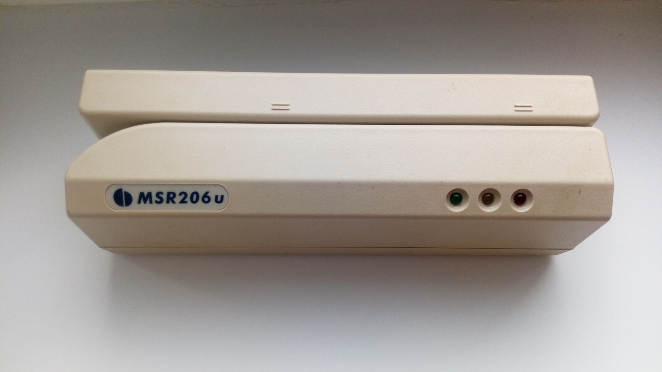
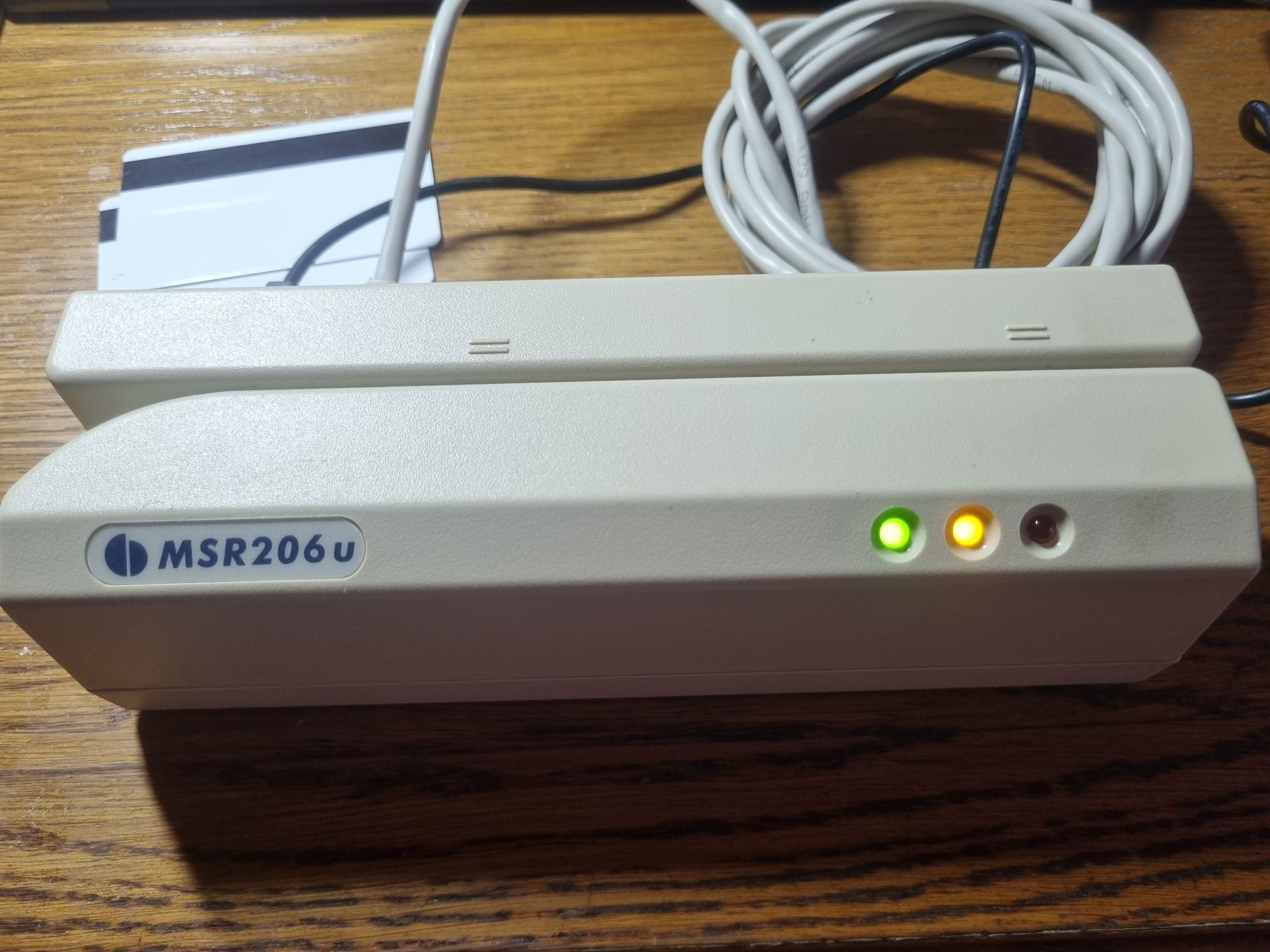
However, I was lucky enough to get a copy. It is called MSR206U. The most advanced model-writes and reads all three tracks, and supports high-precision maps. The device is in good condition, with a power supply (twenty-four volts), but without a USB cable. Well, a great reason to disassemble the device, since I did not find the pinout of the 8P8C connector.
So, the device is somewhat similar to a reader, although about one and a half times larger than usual. Front slot for magnetic card, three indicator LEDs, model designation.
Rubber feet on the bottom, a sticker indicating the model, four screws, one of which is sealed with a warranty seal. I had to tear it off.
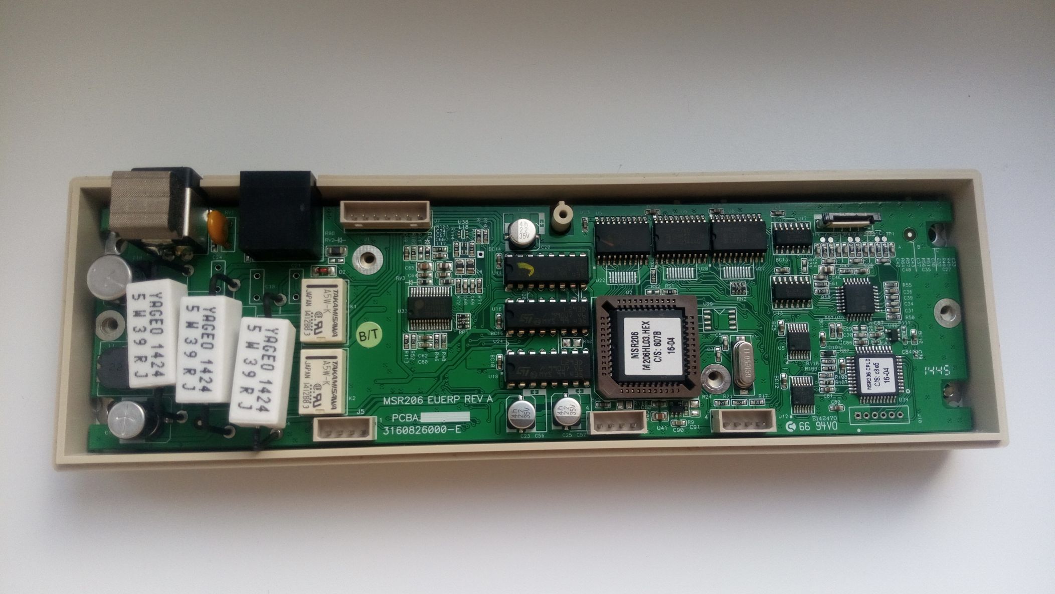
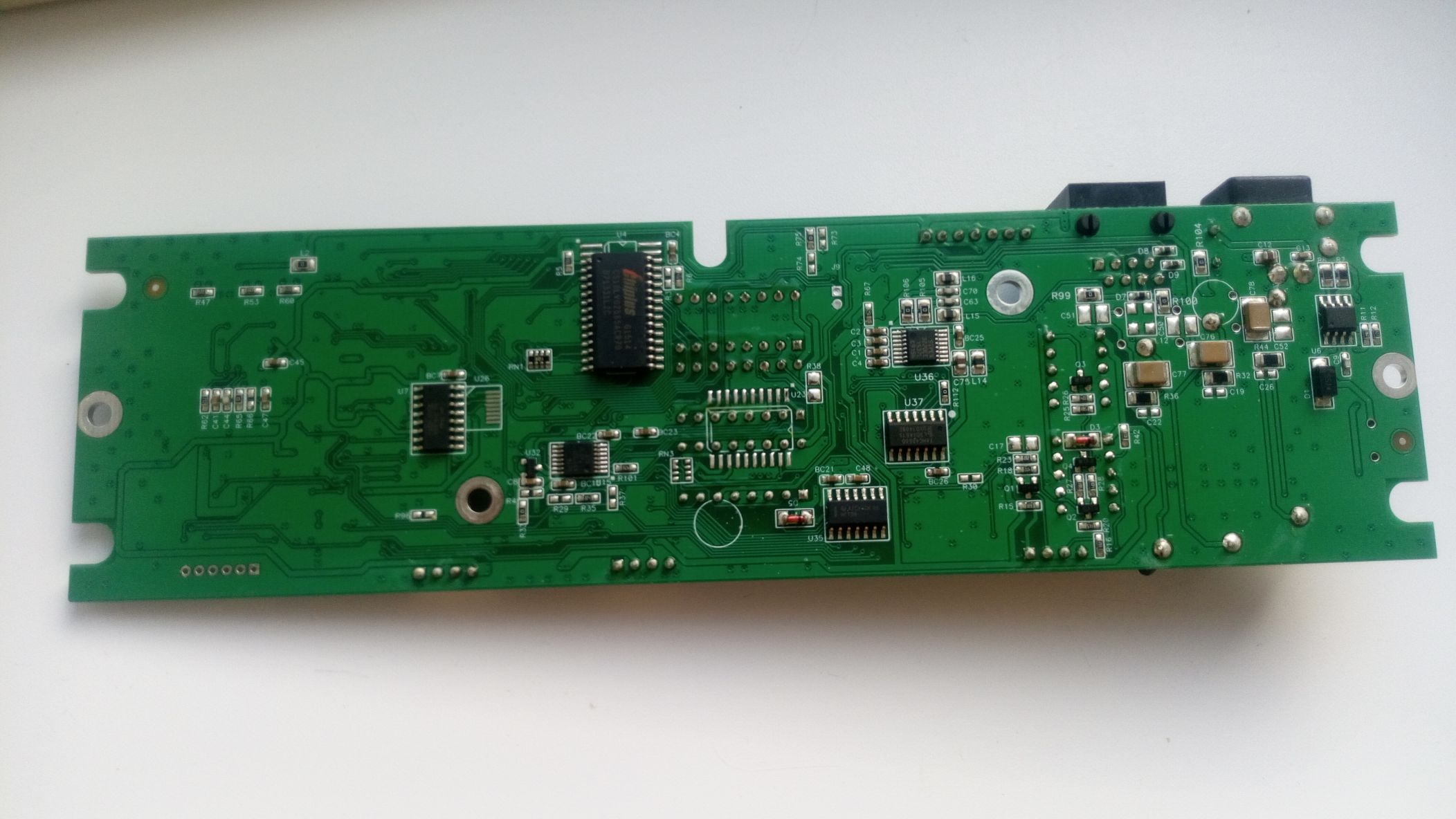
And here's the fee. Powerful resistors, two relays, a microcontroller, and a ROM are clearly visible. The recording head driver deserves special mention: it is made on three L293D H-bridges (presumably, one for each track). The USB interface is implemented on the basis of the USB-TTL Prolific PL-2303HX converter chip.
The pinout, by the way, turned out to be like this:
- Earth
- Not enabled
- Not enabled
- Not enabled
- Not enabled
- 5 V
- D-
- D+
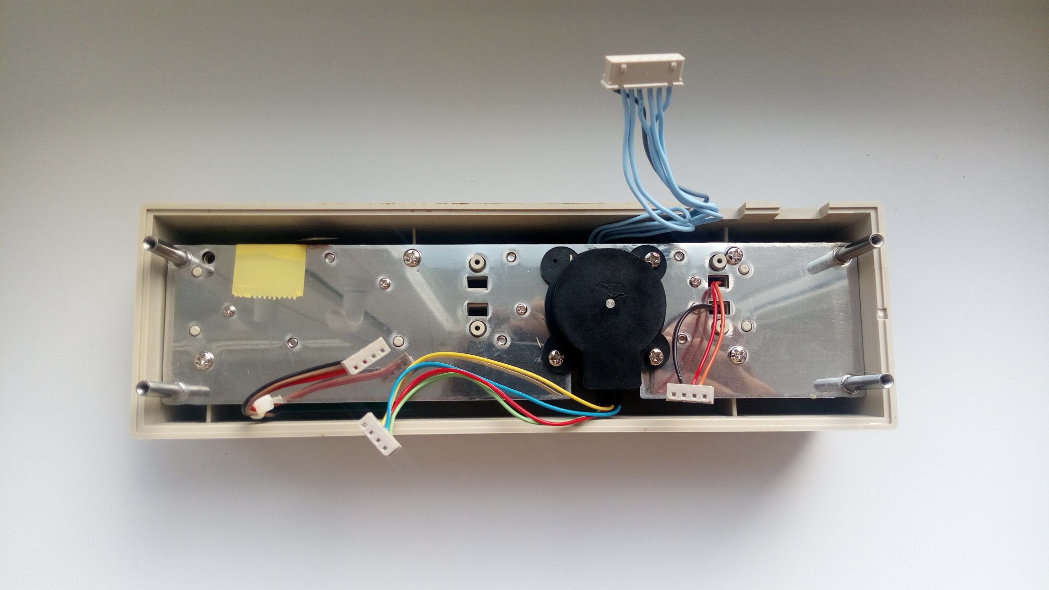
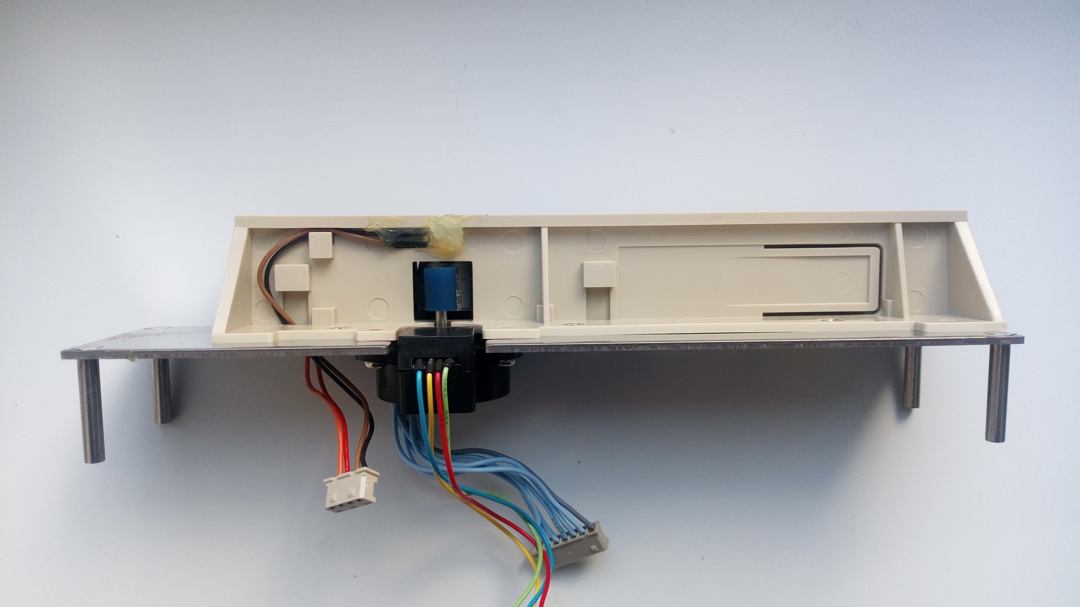
The main part. A small plume (barely visible next to the yellow tape pasted on) from the reader head. A blue wire harness leads to the recording system. The remaining wires lead to an optocoupler that detects when the card is inserted, and indicator LEDs. A black plastic part with colored wires leading to it is an encoder.
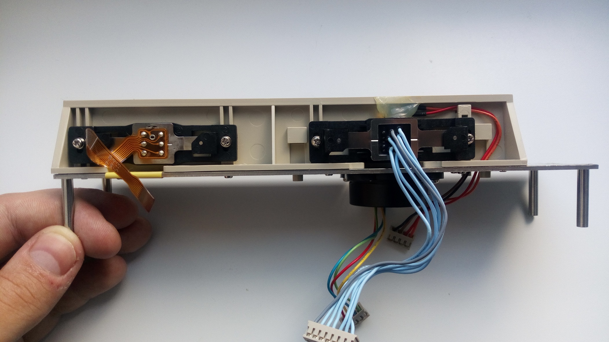
From a different angle. The read and write heads are clearly visible. An optocoupler is neatly fixed above the recording unit in Chinese.
And here's the encoder. On the shaft it has a rubber roller that rotates when the card is rolled and serves to track its position.
White plastic
In addition to the encoder, I also got maps. If that's the case, let's try to write something down.
We put the software supplied with the encoder, 206DDX51. Launching it.
In the settings, specify the COM port, select a high-coercivity card type, enter some data, and click the record button. The yellow LED on the encoder lights up. Now we roll the card, and if recording and verification are successful, the yellow LED will go out, and the green LED will light up. That's it, the map was successfully recorded. We roll it in the reader and make sure that everything is being read successfully.
The emulator
Of course, magnetic cards can be emulated. Many of us even remember the MST feature in some Samsung phones. And now we will try to deal with card emulation and assemble a device for this purpose from just three parts (I already remembered the post of comrade dlinyj about the RFID emulator from three parts). This time, however, everything will be much easier.
There is such a project as MagSpoof. At one time, it was even mentioned here, but all this did not arouse much interest then.
MagSpoof is a magnetic card emulator consisting of a coil, the field of which will be registered by the reader head, the ATtiny85 microcontroller, and the L293D H-bridge already mentioned here.
The project code was written for the Arduino platform and can be run with minimal changes (just change the leg numbers) on almost any board. I just happened to have a Mega handy. This is where we will collect all this stuff. I didn't use the circuit board this time, but placed everything on a solderless breadboard.
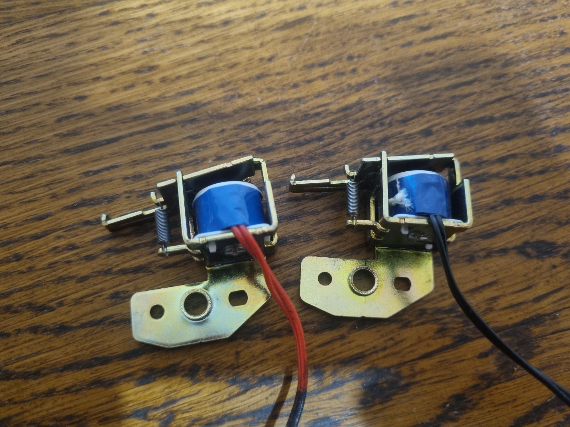
I didn't have a goal to make a fully autonomous device, so I started from what I had. I didn't want to wind up the reel for a device that I would play with for ten minutes and then sort out, so I had to look for something suitable in the bins. By the way, a box with parts from old printers caught my eye. Stepper motors, guides, optocouplers and HVPS boards will be left for some other experiments, but the solenoid, from among those that are in the exciting mechanism of laser printers, will be just right.
We disconnect the moving part from it (carefully, so as not to lose the spring, because we, after all, then put it back), and, in general, that's all.
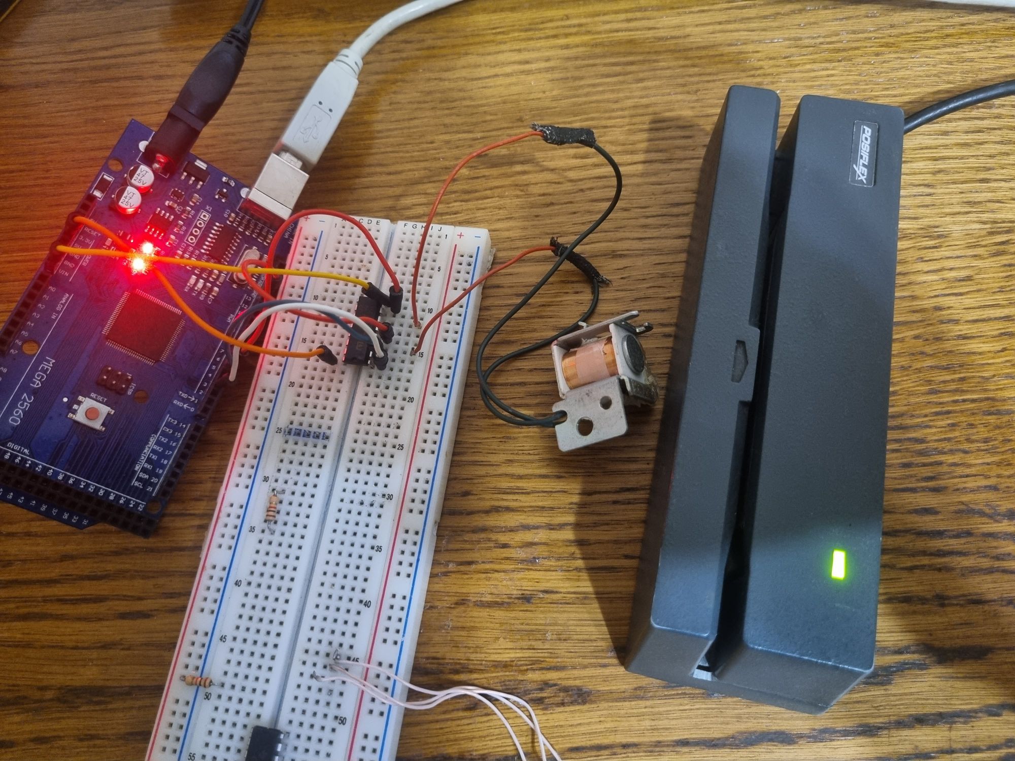
Putting together the diagram. The ENABLE, A and B pins of the L293D are connected to the digital pins of the MK, logic power is connected to five volts, load power is connected to twelve (in general, the solenoid is designed for twenty — four volts, but in this experience I would not supply so much, since you can also magnetize the head itself). Now fill in your map dump and fill in the sketch. Everything, you can try.
We press the coil to the reader, press the button... and everything works successfully the first time, our card number appears in the open Notepad.
Well, where there is a reader, there is a POS-terminal. And it works great on him, too. Everything is as we wanted it to be.
The principle of operation of this emulator is extremely simple — the program calculates the parity and reference value for a given track, and then reproduces it on a reel using an H-bridge that allows you to change the polarity. In theory, if you connect a recording head and an encoder, and connect the current supply not to fixed timings, but to signals from the encoder, you can even create a device for recording cards.
Demagnetization
As a couple of experiments have shown, highly coercive cards are very resistant to being near metal objects and even the short-term presence of a magnet.
Plastic and ferrite magnets could not affect the magnetic stripe at all. It was possible to erase the data only with a neodymium magnet, passing it along the strip.
So it is still not worth carrying magnetic cards in wallets with magnetic fasteners or with some keys (for example, Mottura produced locks whose keys contained neodymium magnets).
Also, do not forget about the banal wear and tear of the card. At one time, the Maestro magnetic cards that were produced were literally stratified from frequent use, of course, while ceasing to be readable.
So what's the bottom line?
In the banking sector, magnetic cards are already going down in history. The largest payment systems have already announced that they will stop issuing magnetic stripe cards in just five years.
And even in other areas where such cards were used, RFID is gradually taking its toll.
Of course, RFID or smart cards are now much easier and cheaper to use. However, I am quite sure that all these materials will be useful to someone.
Links
- Service for generating random card numbers
- Service Code Format
- Library for connecting a magnetic card reader to Arduino
- A similar project from Adafruit (but it didn't work for me personally)
- The simplest magnetic reader circuit
- MagSpoof
- Real-world MagSpoof usage Example
- Software for MSR206
- More MSR206 internals