So, again about plastic cards. Currently, there are many different companies that produce plastic cards and anyone can easily make one for themselves. The information capacity of the card is very limited, but it is quite sufficient to write on it, for example, your first/last name, login, password or some number. For what, you ask? Well, how is it, what is it for - why plastic cards were invented in the first place - for use in authentication systems. You can use the card as a key for a special lock, for authentication when logging into Windows, for authentication in a smart home system, and for many other things. An integral part of any such authentication system will be a card reader, i.e. card reader in our opinion. This is what we will talk about.
Currently, you can find a lot of cheap Chinese magnetic stripe readers on sale, but since buying such things should be uninteresting and unsportsmanlike for real radio junkies, we decided to tell you how to assemble such a reader yourself, on your knees.

So, we will need: a read head from a tape recorder (as in the picture on the left), a thin sheet of PCB, a two-channel op-amp, a PIC16F628A controller, and all sorts of loose items, such as resistors and capacitors.
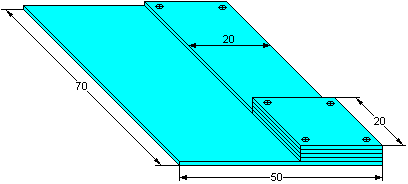
We'll start by making the frame. For the frame, you need to cut out from PCB 1 piece measuring 70x50 mm, 1-2 pieces measuring 70x30 mm, and several more pieces measuring 20x20 mm (so much so that the total thickness of the stacked pieces, except for the first one, is approximately equal to the height of the read head).
Next, all the pieces must be stacked on top of each other, aligned on both sides. You should end up with a layer cake similar to the one in the picture on the right. Now this entire structure needs to be fastened together - glued or drilled holes in the corners and fastened with screws, or something else (it’s better to fasten with screws, at least for the first time, this will make it more convenient to add/subtract layers to adjust the height).
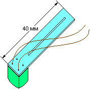
Next, we cut out a strip from the PCB, the width is equal to the width of the read head and about 40 mm long. This will be the head holder. We solder a head with wires to one end, make a slot from the other end to the head, it should look like the picture on the left.
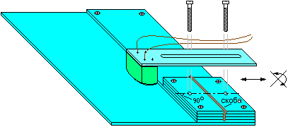
All that remains is to connect the head holder and the frame. In the upper part of the frame, approximately in the middle, you need to fasten a bracket (nail, wire), and drill a hole on both sides of this bracket, the diameter of which coincides with the width of the slot in the head holder. Next, you need to secure the holder to the frame with screws inserted into the drilled holes. It should look like the picture on the right. The thickness of the screws must again match the diameter of the holes and the width of the slot so that the holder does not dangle. It should be able to move only along the axis connecting the centers of the holes. This is necessary to be able to position the head on the magnetic stripe track. By slightly tightening the screws, you can adjust the degree to which the head is pressed against the surface of the frame (the holder resting on the bracket will bend a little more or a little less).
Well, the frame is ready, you can move on to the circuit and printed circuit board.
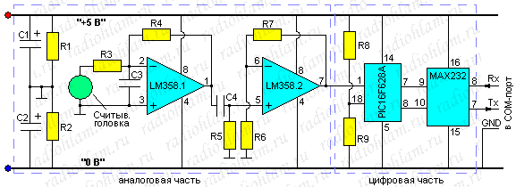
The diagram of our card reader is shown in the figure on the left.
As you can see, this device can be divided into two parts: analog and digital. The analog part consists of a read head and a two-stage amplifier made on a dual LM358 op-amp. The digital part consists of a controller and interface converter on the MAX232 chip, which allows you to transfer information from the controller to a computer or another controller via the RS-232 interface. In order not to overload the diagram, the MAX232 harness is not drawn, it can be viewed in the datasheet or here.
The controller's task is to count the time intervals between changes in the signal level from the head (in other words, to measure the time between edges) and transmit them to the computer. For these purposes, a comparator built into the controller is used, one input of which is supplied with a signal from the amplifier, and the other is supplied with a reference level from a resistor divider. The controller measures the time between interrupts from the comparator. Next, the computer program reconstructs the original binary signal from these time intervals, and then decodes it.
The fully assembled device looks like this :
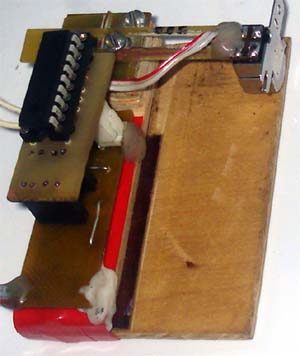
As you can see, the controller had to be placed on a separate board from the analog part and the interface converter. This made it possible to expand the controller and make the electronic part as a whole less wide (less than 20 mm, so that it fits on the side of the head holder). The boards are placed one above the other and connected using a 5-pin connector (not so in the photo, but I just didn’t have a connector).
You can read in detail about receiving and decoding F/2F frequency encoded signals here (we are dealing with just such signals and implementing exactly the same algorithm as in that article), but about where and in what format they are usually recorded on the card the data is here.
Download PCB (DipTrace 2.0)
Download program sources for the controller (asm)
Download the source code for the computer program (C++ Builder)
The computer program decodes the intervals between pulses recorded in the log file using the RH_Com program (in hex format). This program is given simply as an example; it only implements decoding of five-bit encoding; there is no control over the correctness of reading by parity and LRC.
Currently, you can find a lot of cheap Chinese magnetic stripe readers on sale, but since buying such things should be uninteresting and unsportsmanlike for real radio junkies, we decided to tell you how to assemble such a reader yourself, on your knees.

So, we will need: a read head from a tape recorder (as in the picture on the left), a thin sheet of PCB, a two-channel op-amp, a PIC16F628A controller, and all sorts of loose items, such as resistors and capacitors.

We'll start by making the frame. For the frame, you need to cut out from PCB 1 piece measuring 70x50 mm, 1-2 pieces measuring 70x30 mm, and several more pieces measuring 20x20 mm (so much so that the total thickness of the stacked pieces, except for the first one, is approximately equal to the height of the read head).
Next, all the pieces must be stacked on top of each other, aligned on both sides. You should end up with a layer cake similar to the one in the picture on the right. Now this entire structure needs to be fastened together - glued or drilled holes in the corners and fastened with screws, or something else (it’s better to fasten with screws, at least for the first time, this will make it more convenient to add/subtract layers to adjust the height).

Next, we cut out a strip from the PCB, the width is equal to the width of the read head and about 40 mm long. This will be the head holder. We solder a head with wires to one end, make a slot from the other end to the head, it should look like the picture on the left.

All that remains is to connect the head holder and the frame. In the upper part of the frame, approximately in the middle, you need to fasten a bracket (nail, wire), and drill a hole on both sides of this bracket, the diameter of which coincides with the width of the slot in the head holder. Next, you need to secure the holder to the frame with screws inserted into the drilled holes. It should look like the picture on the right. The thickness of the screws must again match the diameter of the holes and the width of the slot so that the holder does not dangle. It should be able to move only along the axis connecting the centers of the holes. This is necessary to be able to position the head on the magnetic stripe track. By slightly tightening the screws, you can adjust the degree to which the head is pressed against the surface of the frame (the holder resting on the bracket will bend a little more or a little less).
Well, the frame is ready, you can move on to the circuit and printed circuit board.

The diagram of our card reader is shown in the figure on the left.
- R1=R2=R9=1 kOhm
- R3=R8=1.5 kOhm
- R4=100 kOhm
- R5=10 kOhm
- R6=4.7 kOhm
- R7=470 kOhm
- C1=C2=1 µF
- C3=1 nF
- C4=0.1 µF
As you can see, this device can be divided into two parts: analog and digital. The analog part consists of a read head and a two-stage amplifier made on a dual LM358 op-amp. The digital part consists of a controller and interface converter on the MAX232 chip, which allows you to transfer information from the controller to a computer or another controller via the RS-232 interface. In order not to overload the diagram, the MAX232 harness is not drawn, it can be viewed in the datasheet or here.
The controller's task is to count the time intervals between changes in the signal level from the head (in other words, to measure the time between edges) and transmit them to the computer. For these purposes, a comparator built into the controller is used, one input of which is supplied with a signal from the amplifier, and the other is supplied with a reference level from a resistor divider. The controller measures the time between interrupts from the comparator. Next, the computer program reconstructs the original binary signal from these time intervals, and then decodes it.
The fully assembled device looks like this :

As you can see, the controller had to be placed on a separate board from the analog part and the interface converter. This made it possible to expand the controller and make the electronic part as a whole less wide (less than 20 mm, so that it fits on the side of the head holder). The boards are placed one above the other and connected using a 5-pin connector (not so in the photo, but I just didn’t have a connector).
You can read in detail about receiving and decoding F/2F frequency encoded signals here (we are dealing with just such signals and implementing exactly the same algorithm as in that article), but about where and in what format they are usually recorded on the card the data is here.
Download PCB (DipTrace 2.0)
Download program sources for the controller (asm)
Download the source code for the computer program (C++ Builder)
The computer program decodes the intervals between pulses recorded in the log file using the RH_Com program (in hex format). This program is given simply as an example; it only implements decoding of five-bit encoding; there is no control over the correctness of reading by parity and LRC.
