
Tomcat
Professional
- Messages
- 2,688
- Reaction score
- 1,037
- Points
- 113
Greetings to all!
Many of us have read at least once how banking transactions are processed. And we all know that an unencrypted PIN does not go anywhere beyond the pin pad. But there is traditionally not enough information about how exactly this is implemented.
So, during this article we will talk about pin pads. Let's find out how they work and what protection they have. Using a real device as an example, let’s look at its management. As usual, there will be a lot of interesting things.
In the comments to my post about magnetic cards, many were interested in the transaction processing process. So I decided to write about this, especially since the topic of how such devices work has interested me for a long time.
POS terminals like VeriFone Tranz or VeriFone OMNI have long since become history. The vast majority of payment terminals are now equipped with a device for entering and encrypting a PIN (in most cases it is built-in).

So, a pin pad (PIN Entry Device) is a device that has a secure key storage (we’ll talk about how this is implemented a little later), allowing the user to enter a PIN and return its encrypted value. For use in the banking industry, they undergo PCI PED (Payment Card Industry PIN Entry Device) certification. The pin pad can be either external, made as a separate device, or built-in, implemented by the terminal’s circuitry.
Separately, there are so-called smart pin pads, which are almost full-fledged POS terminals, adapted for control from a cash register computer.
The VeriFone PINpad 1000SE (aka just PP1000SE) was taken as the main piece of hardware that will appear in this article. The model is quite old, after the decommissioning of terminals without contactless payment support (CTLS), it is found a little less often than anywhere else, although in better times they were installed almost everywhere. Why him? The thing is that payment terminals and the banking sector are, in principle, a very closed area. And finding any software, documentation, and even more so development tools is extremely problematic. The same cannot be said about our device, the necessary information for which was found without any problems.

Actually, this is what he looks like. I think many of you will even remember it. On the front panel it has a display (graphic, but used only in text mode, and only eight characters fit on the display), buttons for entering a PIN, canceling, adjusting and confirming, as well asunnecessary buttons, programmable function keys (which, by the way, the only publicly available manual says something like “This feature is not implemented in this version of firmware).

On the reverse side there is a sticker with the model name, rubber feet, a tweeter hole, and a mounting bracket for mounting on a stand. Well, a 4P4C type connector for connecting the cable.
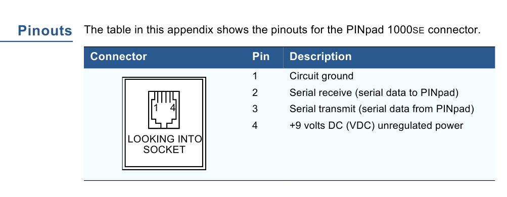
The pinout of this connector is given in the documentation. She's here like this.

Let's sort it out. The electronics are covered with a protective plate. A long-dead CR2450 battery is also visible. It must be replaced with a new one, otherwise the pin pad will not show any signs of life when power is applied.

Remove the protective plate. A certain proprietary chip, a couple of microcircuits from ST and Cypress, and some discrete logic are clearly visible. This very proprietary chip is either something custom-made, or general-purpose microcircuits, on which, instead of the usual one, the company’s marking is applied at the factory. Older copies did not have such components; most often Z80/MC68000 with appropriate wiring were used.
The keys themselves are usually stored in SRAM, so when the battery runs out they will also disappear along with all the parameters.

Let's open the board. The display is graphic, without markings. I couldn’t tear it away from the plastic fastening; I was afraid to break it.
So, as we remember, the pin pad must have a secure key storage. In particular, this means that if you try to gain access, the keys will be irreversibly erased. For this purpose, special anti-tampering systems are used. In addition to control systems, various design solutions are used that complicate non-destructive disassembly of the device or even make it impossible. Let's show you what they look like.

Let's look at the same plate that covers the electronics. This is not just a piece of PCB. Inside it, a thin snake path runs across its entire area. If you try to drill or pick a hole in it, the circuit will open and the safety circuit will be broken. The plate is connected to the board using pieces of anisotropic rubber, similar to what is used to connect to the contacts on the board of segment LCDs.

In addition to plates, there are also frames. providing control of the connection between two boards. Here is an example of such a frame in the VeriFone SC5000 pin pad. A cable is glued along its perimeter, connected to the board using the same rubber band. The pressing density of the boards is also controlled - for this there is another piece of contact rubber connecting the boards directly.

And here is another pin-pad, Ingenico 3050. The cable with that same snake track glued to the back of the cover is clearly visible.

Well, don’t forget about the banal limit switches. Here they are presented in the form of rubber buttons pressed by parts of the body. One of them is located right among the protective plate, four more are located on the keyboard side. Here, too, everything is not so simple: around each pad there is also a ring contact connected to ground (note that ordinary buttons are not equipped with this). If an intruder tries to insert foil or inject conductive liquid, the security circuit will be shorted to ground, which, of course, will be immediately perceived as a break-in.
Older pin pads used tact buttons and microswitches for these purposes.


Protection methods also include filling with resin. Nowadays, this rarely happens in POS terminals, but ATM keyboards still often flood. Sometimes, instead of completely packaging the device into a single monolith of epoxy, it is simply poured on top of the board (in shape or just as a drop), protecting its individual sections.

Let's return to our Ingenico 3050. On top of the motherboard, another one is soldered upside down, on which the control chips are located. Because of this design, dismantling this assembly without tearing off the tracks or overheating the microcircuits is not so easy, especially considering that in addition to soldering, it is also glued.

And here is the POS-terminal Ingenico 5100. Its processor and its hardware are located inside a single resin monolith. Only the connection contacts stick out.
ATM pin pad. Combined protection is used here - a board placed in a safety circuit, filled with resin on top.


Newer pin pad, EPPV6. The compartments in the body filled with resin are clearly visible, as well as the hole where it was poured. The hole sealed with a “Kill EPP” sticker is a self-destruct button (when pressed, the keys are erased and the device is blocked), pressed when the unit is taken out of service.
In addition to hardware, there are also software protection methods: secure bootloaders, encrypted firmware, software signing.

So, the battery is soldered, you can try connecting it. For convenience, I soldered an adapter to which the pin pad is connected using a regular twisted cable with 4P4C connectors at the ends from the landline telephone handset.
We serve food. The pin pad should squeak and write something like “Tampered device” (well, or not write if the battery has survived to this day and you did not have to change it). Click “Cancel” several times and get into working mode. If any string is loaded there, it will display it, but if not, then a running arrow will appear on the screen.
Press the key combination “Cancel” + “2”, enter the password 844747746 and get to the service menu. The list of items there is as follows:
You need to select by pressing the number key with the corresponding number.
There is also a combination “Cancel” + “3” with the password 83746, but there is nothing interesting for us there.
You may ask: why is the graphic screen used so irrationally? Wouldn't it be better for the developers to install a segment display?

Everything is very simple. There was also a “narrow” version PP1000SE, which was older. There is a segment screen, and the last two menu items are missing. In better times, VeriFone acquired the Israeli company Lipman Electronics Engineering, which produced Nurit terminals. Accordingly, part of its developments was used in the PP1000SE second version. And for the sake of compatibility with the first, such measures were introduced.
The “wide” PP1000SE can be switched to Nurit mode (if anything, to exit from there you must first press the middle purple button and then “2”, the password is the same), on it you can also exit to Nurit OS by selecting the last menu item , and then hold down the keys “3” + “5” + “7”.


And here is an antique pin pad PP1000+. The command system is similar to PP1000SE. By the way, the resin is visible inside.
PP1000SE is controlled by data packets. The beginning is the symbol “SI” or “STX”, the end is “SO” or “ETX”. Which of the two to choose is indicated in the table of the format of each package in the manual.
After the data packet there is a control value - a sequential XOR of all bytes of the packet, except for the initial one.
Function to calculate this value
If the checksum matches, the pin pad responds with an “ACK” byte; if not, it sends a “NAK” byte. After three non-matches in a row, "EOT" is sent.
It is also worth noting the port parameters - 7 data bits, even parity. The speed is set in the same menu.
Using text output as an example, let's look at sending a packet.
So, a package of type Z2 is used to output text. First, the symbol “STX” is added to the line (for convenience, I indicated the codes of all these symbols at the beginning of the program via define ), then the package code “Z2”, then the symbol “SUB”, which serves to clear the screen, the line itself for output, the symbol “ ETX." The check number is calculated and also added.
So let's try:
Program to print a string
We launch it, and if everything was connected correctly, something like the following should appear on the display:

Of course, this also works on a “narrow” pin pad:


Well, it’s time to move on to the most important thing - how exactly encryption is done. Most pin pads use the 3DES algorithm. Previously, simple DES was used, but now you can hardly find it anywhere.
So, in terminal software you can find mainly three types of keys: PIN, MAC and KLK. The first from this list is the key directly for PIN encryption. The second is the Message Authentication Code key, which allows you to track the authenticity of sent data packets. The third is Key Loading Key, a key for loading keys that allows you to load already encrypted keys for greater security. Of all three, we are most interested in the PIN key.
There are two methods of working with keys - Master/Session and DUKPT. Currently, the second option is mainly used.
Master/Session is already a fairly old method. The principle of its operation is this: inside the pin pad in a secure storage there is a master key. The terminal contains in its memory a working (session) key encrypted with a master key. If it is necessary to encrypt something, the terminal sends this working key to the pinpad, where it is decrypted with the master key. An encrypted block of data is returned. In this case, neither the master key nor the decrypted working key leaves the pin pad.
DUKPT is a more advanced option. Its essence is that, with the help of BDK (Base Derivation Key), IPEK (Initial PIN Encryption Key) and KSN (Key Serial Number) are generated, which are loaded into the pin pad. IPEK-based keys are issued that are already used in the encryption process.
With each encryption operation, KSN is incremented by one, and the pin pad returns the encrypted block of data and the new KSN value.
In this example, we will consider the Master/Session method as the easiest to implement.
So, for loading keys into the pin pad there is a package “02”. Next, you need to indicate the number of the cell where the key will be loaded, and, in fact, the key itself.
Something like that
For example, I will load the key 0123456789ABCDEF there . This packet is slightly different in format: after the pin pad responds, you must send “ACK”, otherwise the key will not be filled.
After loading the key, the “Tampered device” message will also disappear.

Of course, the pin pad encrypts not just a PIN, but a PIN-block - a special data packet. The most commonly used is ISO 9564 Format 0, which is the result of XORing the PAN and PIN data.
Well, time to try reading the PIN.
First, let's prepare the input data. Let's take the same PAN that was in the post about magnetic cards - 4034351574462072 . Let the working key be 0123456789012345 . Let's encrypt it using the previously specified master key, obtaining the value 59216EC9E36F8EF8 .
The PIN will be the banal 1234. Based on PAN and PIN, we will calculate PIN-block: 041277AEA8BB9DF8 .
We are writing another program. First, you need to select a master key, for which we send a packet with code 08. After sending an input request, the pin pad requests a PIN, after which it sends an encrypted PIN-block. At this time, the display shows the words “PROCESSING” and “PIN PAD”, which will remain there until the “Cancel” button is pressed or a new package arrives. After receiving the PIN-block, we will send the “Indicate host done” packet (with code Q2), which will display the message “Thank you” on the pin-pad screen.
The functions ended up looking like this:
Let's launch. We enter our PIN - 1234. The pin pad responds by sending us PIN-block 5DCB16E4555C6B1A . We decrypt it using our unencrypted working key and get our calculated value 041277AEA8BB9DF8 .
It's alive, it works!
I also happened to get my hands on a PP1000SE CTLS. It differs from the usual one in the slot for the SAM module and the presence of a contactless reader. Alas, I was unable to find any commands regarding card reading...


But here is such a copy in action, the photo was taken in Greece in the summer of two thousand and twenty-one:

So we looked at another component of processing plastic cards. At the same time, they demonstrated how to launch such devices in “laboratory” conditions.
I’m definitely sure that someone will like all these materials, especially since almost no one has done such a description of such equipment.
Many of us have read at least once how banking transactions are processed. And we all know that an unencrypted PIN does not go anywhere beyond the pin pad. But there is traditionally not enough information about how exactly this is implemented.
So, during this article we will talk about pin pads. Let's find out how they work and what protection they have. Using a real device as an example, let’s look at its management. As usual, there will be a lot of interesting things.
❯ The point is
In the comments to my post about magnetic cards, many were interested in the transaction processing process. So I decided to write about this, especially since the topic of how such devices work has interested me for a long time.
POS terminals like VeriFone Tranz or VeriFone OMNI have long since become history. The vast majority of payment terminals are now equipped with a device for entering and encrypting a PIN (in most cases it is built-in).
So, a pin pad (PIN Entry Device) is a device that has a secure key storage (we’ll talk about how this is implemented a little later), allowing the user to enter a PIN and return its encrypted value. For use in the banking industry, they undergo PCI PED (Payment Card Industry PIN Entry Device) certification. The pin pad can be either external, made as a separate device, or built-in, implemented by the terminal’s circuitry.
Separately, there are so-called smart pin pads, which are almost full-fledged POS terminals, adapted for control from a cash register computer.
❯ Equipment overview
The VeriFone PINpad 1000SE (aka just PP1000SE) was taken as the main piece of hardware that will appear in this article. The model is quite old, after the decommissioning of terminals without contactless payment support (CTLS), it is found a little less often than anywhere else, although in better times they were installed almost everywhere. Why him? The thing is that payment terminals and the banking sector are, in principle, a very closed area. And finding any software, documentation, and even more so development tools is extremely problematic. The same cannot be said about our device, the necessary information for which was found without any problems.
Actually, this is what he looks like. I think many of you will even remember it. On the front panel it has a display (graphic, but used only in text mode, and only eight characters fit on the display), buttons for entering a PIN, canceling, adjusting and confirming, as well as
On the reverse side there is a sticker with the model name, rubber feet, a tweeter hole, and a mounting bracket for mounting on a stand. Well, a 4P4C type connector for connecting the cable.
The pinout of this connector is given in the documentation. She's here like this.
Let's sort it out. The electronics are covered with a protective plate. A long-dead CR2450 battery is also visible. It must be replaced with a new one, otherwise the pin pad will not show any signs of life when power is applied.
Remove the protective plate. A certain proprietary chip, a couple of microcircuits from ST and Cypress, and some discrete logic are clearly visible. This very proprietary chip is either something custom-made, or general-purpose microcircuits, on which, instead of the usual one, the company’s marking is applied at the factory. Older copies did not have such components; most often Z80/MC68000 with appropriate wiring were used.
The keys themselves are usually stored in SRAM, so when the battery runs out they will also disappear along with all the parameters.
Let's open the board. The display is graphic, without markings. I couldn’t tear it away from the plastic fastening; I was afraid to break it.
❯ Protection methods
So, as we remember, the pin pad must have a secure key storage. In particular, this means that if you try to gain access, the keys will be irreversibly erased. For this purpose, special anti-tampering systems are used. In addition to control systems, various design solutions are used that complicate non-destructive disassembly of the device or even make it impossible. Let's show you what they look like.
Let's look at the same plate that covers the electronics. This is not just a piece of PCB. Inside it, a thin snake path runs across its entire area. If you try to drill or pick a hole in it, the circuit will open and the safety circuit will be broken. The plate is connected to the board using pieces of anisotropic rubber, similar to what is used to connect to the contacts on the board of segment LCDs.
In addition to plates, there are also frames. providing control of the connection between two boards. Here is an example of such a frame in the VeriFone SC5000 pin pad. A cable is glued along its perimeter, connected to the board using the same rubber band. The pressing density of the boards is also controlled - for this there is another piece of contact rubber connecting the boards directly.
And here is another pin-pad, Ingenico 3050. The cable with that same snake track glued to the back of the cover is clearly visible.
Well, don’t forget about the banal limit switches. Here they are presented in the form of rubber buttons pressed by parts of the body. One of them is located right among the protective plate, four more are located on the keyboard side. Here, too, everything is not so simple: around each pad there is also a ring contact connected to ground (note that ordinary buttons are not equipped with this). If an intruder tries to insert foil or inject conductive liquid, the security circuit will be shorted to ground, which, of course, will be immediately perceived as a break-in.
Older pin pads used tact buttons and microswitches for these purposes.
Protection methods also include filling with resin. Nowadays, this rarely happens in POS terminals, but ATM keyboards still often flood. Sometimes, instead of completely packaging the device into a single monolith of epoxy, it is simply poured on top of the board (in shape or just as a drop), protecting its individual sections.
Let's return to our Ingenico 3050. On top of the motherboard, another one is soldered upside down, on which the control chips are located. Because of this design, dismantling this assembly without tearing off the tracks or overheating the microcircuits is not so easy, especially considering that in addition to soldering, it is also glued.
And here is the POS-terminal Ingenico 5100. Its processor and its hardware are located inside a single resin monolith. Only the connection contacts stick out.
ATM pin pad. Combined protection is used here - a board placed in a safety circuit, filled with resin on top.
Newer pin pad, EPPV6. The compartments in the body filled with resin are clearly visible, as well as the hole where it was poured. The hole sealed with a “Kill EPP” sticker is a self-destruct button (when pressed, the keys are erased and the device is blocked), pressed when the unit is taken out of service.
In addition to hardware, there are also software protection methods: secure bootloaders, encrypted firmware, software signing.
❯ First use
So, the battery is soldered, you can try connecting it. For convenience, I soldered an adapter to which the pin pad is connected using a regular twisted cable with 4P4C connectors at the ends from the landline telephone handset.
We serve food. The pin pad should squeak and write something like “Tampered device” (well, or not write if the battery has survived to this day and you did not have to change it). Click “Cancel” several times and get into working mode. If any string is loaded there, it will display it, but if not, then a running arrow will appear on the screen.
Press the key combination “Cancel” + “2”, enter the password 844747746 and get to the service menu. The list of items there is as follows:
- PC MEM TST - NVRAM test (with its complete erasure)
- INIT MKEY RAM - deleting keys
- LANGUAGES - well, it’s clear what it is
- DSP ALL MSG - message display mode
- SET BAUD RATE - port speed
- SET KEY MGT - key organization mode
- SET PP MODE - pin pad operating mode (Nurit/VeriFone)
- OS ACCESS - exit to Nurit OS (NOS)
You need to select by pressing the number key with the corresponding number.
There is also a combination “Cancel” + “3” with the password 83746, but there is nothing interesting for us there.
❯ What's wrong with the screen?
You may ask: why is the graphic screen used so irrationally? Wouldn't it be better for the developers to install a segment display?
Everything is very simple. There was also a “narrow” version PP1000SE, which was older. There is a segment screen, and the last two menu items are missing. In better times, VeriFone acquired the Israeli company Lipman Electronics Engineering, which produced Nurit terminals. Accordingly, part of its developments was used in the PP1000SE second version. And for the sake of compatibility with the first, such measures were introduced.
The “wide” PP1000SE can be switched to Nurit mode (if anything, to exit from there you must first press the middle purple button and then “2”, the password is the same), on it you can also exit to Nurit OS by selecting the last menu item , and then hold down the keys “3” + “5” + “7”.
And here is an antique pin pad PP1000+. The command system is similar to PP1000SE. By the way, the resin is visible inside.
❯ Control packages
PP1000SE is controlled by data packets. The beginning is the symbol “SI” or “STX”, the end is “SO” or “ETX”. Which of the two to choose is indicated in the table of the format of each package in the manual.
After the data packet there is a control value - a sequential XOR of all bytes of the packet, except for the initial one.
Function to calculate this value
Code:
uint8_t BCC(string data) {
uint8_t temp = data[1];
for(int i = 2; i < data.length(); i++) temp ^= data[i];
return temp;
}
If the checksum matches, the pin pad responds with an “ACK” byte; if not, it sends a “NAK” byte. After three non-matches in a row, "EOT" is sent.
It is also worth noting the port parameters - 7 data bits, even parity. The speed is set in the same menu.
❯ Displaying text on the screen
Using text output as an example, let's look at sending a packet.
Code:
void showString(string s) {
   uint8_t data = 0;
   string input = "";
   input += STX;
   input += "Z2";
   input += 0x1A;
   input += s;
   input += ETX;
   input += BCC(input);
   WriteStringCOM(input);
   while(!ReadCOM(data));;
   if(data != 0x06) cout << "error" << endl;
   else cout << "success";
}
So, a package of type Z2 is used to output text. First, the symbol “STX” is added to the line (for convenience, I indicated the codes of all these symbols at the beginning of the program via define ), then the package code “Z2”, then the symbol “SUB”, which serves to clear the screen, the line itself for output, the symbol “ ETX." The check number is calculated and also added.
So let's try:
Program to print a string
Code:
#include <iostream>
#include <windows.h>

using namespace std;

#define STX 0x02
#define ETX 0x03
#define SI 0x0F
#define SO 0x0E
#define ACK 0x06
#define EOT 0x04
#define NAK 0x15

HANDLE hSerial;

uint8_t openPort(int portNumber) {
char sPortName[10];
sprintf (sPortName, "COM%i", portNumber);
hSerial = ::CreateFile(sPortName, GENERIC_READ | GENERIC_WRITE, 0, 0, OPEN_EXISTING, FILE_ATTRIBUTE_NORMAL, 0);
DCB dcbSerialParams = { 0 };
dcbSerialParams.DCBlength = sizeof(dcbSerialParams);
if(!GetCommState(hSerial, &dcbSerialParams)){
cout << "getting state error\n";
exit(0);
    }
dcbSerialParams.BaudRate = CBR_1200;
dcbSerialParams.ByteSize = 7;
dcbSerialParams.StopBits = ONESTOPBIT;
dcbSerialParams.Parity = EVENPARITY;
if(!SetCommState(hSerial, &dcbSerialParams)){
cout << "error setting serial port state\n";
exit(0);
    }

cout << "Opened port: " << sPortName << endl;
return 1;
}

uint8_t ReadCOM(uint8_t & sReceivedByte) {
DWORD iSize;
ReadFile(hSerial, &sReceivedByte, 1, &iSize, 0);  // получаем 1 байт
return iSize;
    }

DWORD WriteCOM(uint8_t data) {
DWORD dwBytesWritten;    // тут будет количество собственно переданных байт
DWORD dwSize = 1;
WriteFile(hSerial, &data, dwSize, &dwBytesWritten, NULL);
return dwBytesWritten;
}

void WriteStringCOM(string data) {
for(int i = 0; i < data.length(); i++) WriteCOM(data[i]);
}

uint8_t BCC(string data) {
char temp = data[1];
for(int i = 2; i < data.length(); i++) temp ^= data[i];
return temp;
}

void showString(string s) {
uint8_t data = 0;
string input = "";
input += STX;
input += "Z2";
input += 0x1A;
input += s;
input += ETX;
input += BCC(input);
WriteStringCOM(input);
while(!ReadCOM(data));;
if(data != 0x06) cout << "error" << endl;
else cout << "success";
}

int main()
{
openPort(4);
showString("HABR.COM");
return 0;
}
We launch it, and if everything was connected correctly, something like the following should appear on the display:
Of course, this also works on a “narrow” pin pad:
❯ Keys
Well, it’s time to move on to the most important thing - how exactly encryption is done. Most pin pads use the 3DES algorithm. Previously, simple DES was used, but now you can hardly find it anywhere.
So, in terminal software you can find mainly three types of keys: PIN, MAC and KLK. The first from this list is the key directly for PIN encryption. The second is the Message Authentication Code key, which allows you to track the authenticity of sent data packets. The third is Key Loading Key, a key for loading keys that allows you to load already encrypted keys for greater security. Of all three, we are most interested in the PIN key.
❯Key organization
There are two methods of working with keys - Master/Session and DUKPT. Currently, the second option is mainly used.
Master/Session is already a fairly old method. The principle of its operation is this: inside the pin pad in a secure storage there is a master key. The terminal contains in its memory a working (session) key encrypted with a master key. If it is necessary to encrypt something, the terminal sends this working key to the pinpad, where it is decrypted with the master key. An encrypted block of data is returned. In this case, neither the master key nor the decrypted working key leaves the pin pad.
DUKPT is a more advanced option. Its essence is that, with the help of BDK (Base Derivation Key), IPEK (Initial PIN Encryption Key) and KSN (Key Serial Number) are generated, which are loaded into the pin pad. IPEK-based keys are issued that are already used in the encryption process.
With each encryption operation, KSN is incremented by one, and the pin pad returns the encrypted block of data and the new KSN value.
In this example, we will consider the Master/Session method as the easiest to implement.
❯ Load the key
So, for loading keys into the pin pad there is a package “02”. Next, you need to indicate the number of the cell where the key will be loaded, and, in fact, the key itself.
Something like that
Code:
void setMKEY() {
string input = "";
uint8_t data = 0;
input += SI;
input += "02";
input += "0";
input += "0123456789ABCDEF";
input += SO;
input += BCC(input);
WriteStringCOM(input);
for(int i = 0; i < 6; i++) {
while(!ReadCOM(data));;
printf("%02X ",data);
 }
WriteCOM(0x06);
while(!ReadCOM(data));;
printf("%02X ",data);
}
For example, I will load the key 0123456789ABCDEF there . This packet is slightly different in format: after the pin pad responds, you must send “ACK”, otherwise the key will not be filled.
After loading the key, the “Tampered device” message will also disappear.
❯ PIN-block
Of course, the pin pad encrypts not just a PIN, but a PIN-block - a special data packet. The most commonly used is ISO 9564 Format 0, which is the result of XORing the PAN and PIN data.
❯ Requesting a PIN
Well, time to try reading the PIN.
First, let's prepare the input data. Let's take the same PAN that was in the post about magnetic cards - 4034351574462072 . Let the working key be 0123456789012345 . Let's encrypt it using the previously specified master key, obtaining the value 59216EC9E36F8EF8 .
The PIN will be the banal 1234. Based on PAN and PIN, we will calculate PIN-block: 041277AEA8BB9DF8 .
We are writing another program. First, you need to select a master key, for which we send a packet with code 08. After sending an input request, the pin pad requests a PIN, after which it sends an encrypted PIN-block. At this time, the display shows the words “PROCESSING” and “PIN PAD”, which will remain there until the “Cancel” button is pressed or a new package arrives. After receiving the PIN-block, we will send the “Indicate host done” packet (with code Q2), which will display the message “Thank you” on the pin-pad screen.
The functions ended up looking like this:
Code:
void selectMKEY() {
   string input = "";
   input += SI;
   input += "08";
   input += "0"; //номер ячейки ключа
   input += SO;
   input += BCC(input);
   WriteStringCOM(input);
}

void requestPINEntry() {
   uint8_t data = 0;
   string input = "";
   input += STX;
   input += "70";
   input += 0x2E;
   input += "4034351574462072"; //PAN
   input += 0x1C;
   input += "59216EC9E36F8EF8"; //рабочий ключ
   input += "9.99"; //сумма к оплате для отображения на дисплее
   input += ETX;
   input += BCC(input);
   WriteStringCOM(input);
   for(int i = 0; i < 11; i++) {
     while(!ReadCOM(data));;
     printf("%02X ",data);
    }
   for(int i = 0; i < 16; i++) {
     while(!ReadCOM(data));;
     cout << data; //вывод самого PIN-block
    }
    cout << ' ';
   for(int i = 0; i < 2; i++) {
     while(!ReadCOM(data));;
     printf("%02X ",data);
  }
  WriteCOM(0x06);
  Sleep(1000);
  indicateHostDone();
}

void indicateHostDone() {
  string input = "";
  input += STX;
  input += "Q2";
  input += ETX;
  input += BCC(input);
  WriteStringCOM(input);
}
Let's launch. We enter our PIN - 1234. The pin pad responds by sending us PIN-block 5DCB16E4555C6B1A . We decrypt it using our unencrypted working key and get our calculated value 041277AEA8BB9DF8 .
It's alive, it works!
❯ A little about Contactless
I also happened to get my hands on a PP1000SE CTLS. It differs from the usual one in the slot for the SAM module and the presence of a contactless reader. Alas, I was unable to find any commands regarding card reading...
But here is such a copy in action, the photo was taken in Greece in the summer of two thousand and twenty-one:
❯ So what's the bottom line?
So we looked at another component of processing plastic cards. At the same time, they demonstrated how to launch such devices in “laboratory” conditions.
I’m definitely sure that someone will like all these materials, especially since almost no one has done such a description of such equipment.